
User Manual
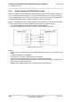
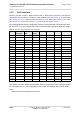
Table Of Contents
- Contents
- Tables
- Figures
- 1 Introduction
- 2 Interface Characteristics
- 2.1 Application Interface
- 2.2 RF Antenna Interface
- 2.3 Sample Application
- 3 Operating Characteristics
- 4 Mechanical Dimensions, Mounting and Packaging
- 5 Regulatory and Type Approval Information
- 6 Document Information
- 7 Appendix

Cinterion
®
ELS31-V/ELS51-V Hardware Interface Overview
2.1 Application Interface
17
ELS31-V_ELS51-V_HIO_v00.502 2015-12-07
Confidential / Preliminary
Page 7 of 35
2.1.2 Serial Interface ASC0
ELS31-V / ELS51-V offers an 8-wire unbalanced, asynchronous modem interface ASC0 con-
forming to ITU-T V.24 protocol DCE signalling. The electrical characteristics do not comply with
ITU-T V.28. The significant levels are 0V (for low data bit or active state) and 1.8V (for high data
bit or inactive state).
ELS31-V / ELS51-V is designed for use as a DCE. Based on the conventions for DCE-DTE
connections it communicates with the customer application (DTE) using the following signals:
• Port TXD @ application sends data to the module’s TXD0 signal line
• Port RXD @ application receives data from the module’s RXD0 signal line
Figure 3: Serial interface ASC0
Features:
• Includes the data lines TXD0 and RXD0, the status lines RTS0 and CTS0 and, in addition,
the modem control lines DTR0, DSR0, DCD0 and RING0.
• Configured for 8 data bits, no parity and 1 stop bit.
• ASC0 can be operated at fixed bit rates from 1200bps up to 921600bps.
• Supports RTS0/CTS0 hardware flow control. Communication is possible by using only RXD
and TXD lines, if RTS0 is pulled low.
• Wake up from SLEEP mode by RTS0 activation (high to low transition).