
User's Manual
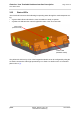
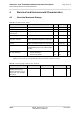
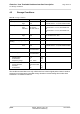
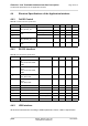
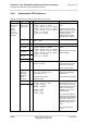
Table Of Contents
- Contents
- Figures
- Tables
- 0 Document History
- 1 Introduction
- 2 Product Concept
- 3 Interface Description
- 4 Electrical and Environmental Characteristics
- 5 Mechanics, Mounting and Packaging
- 6 Full Type Approval
- 7 List of Parts and Accessories
- 8 Appendix A: (Hardware) Watchdog

Cinterion
®
Java Terminals Hardware Interface Description
3.14 RF Antenna Interface
35
EHSxT_BGS5T_HID_v02 2014-08-05
Confidential / Preliminary
Page 35 of 70
3.14 RF Antenna Interface
An external RF antenna is connected via the Java Terminals’s female SMA connector that is
also the antenna reference point (ARP).
Figure 12: Antenna connector
The system impedance is 50. In any case, for good RF performance, the return loss of the
customer application’s antenna should be better than 10dB (VSWR < 2). Java Terminals with-
stand a total mismatch at this connector when transmitting with power control level for maxi-
mum RF power.
Inside the Java module an inductor to ground provides additional ESD protection to the anten-
na connector. To protect the inductor from damage no DC voltage must be applied to the an-
tenna circuit.
For the application it is recommended to use an antenna with an SMA (male) connector:
Please note that the terminal should be installed and operated with a minimum distance of
20cm between the antenna connected to the terminal and any human bodies. Also, the trans-
mitter must not be co-located or operating in conjunction with any other antenna or transmitter.
The allowed maximum antenna gain (including cable loss) for stand-alone situation is given be-
low in Table 14.
Table 14: Allowed maximum antenna gain (including cable loss)
Module 850MHz 900MHz 1800MHz 1900MHz 2100MHz
EHS6T USB 3.42dBi 4.18dBi 9.64dBi 2.51dBi 15.54dBi
BGS5T USB 2.15dBi 2.15dBi 2.15dBi 2.15dBi na
EHS5T RS485 na 6.10dBi 12.30dBi na 12.30dBi