
User Manual
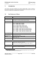
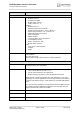
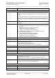
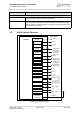
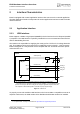
Table Of Contents

EHS6 Hardware Interface Overview
1.2 EHS6 System Overview
9
EHS6_HIO_v01.441 Page 9 of 38 2013-07-11
Confidential / Preliminary
1.2 EHS6 System Overview
Figure 1: EHS6 system overview
Evaluation kit
Evaluation module EHS6 module soldered onto a dedicated PCB that can be connected to an
adapter in order to be mounted onto the DSB75.
DSB75 DSB75 Development Support Board designed to test and type approve
Cinterion Wireless Modules and provide a sample configuration for applica-
tion engineering. A special adapter is required to connect the EHS6 evalu-
ation module to the DSB75.
Feature Implementation
GPIO
interface
I2C
USB
ASC0 lines
HSIC LPM/
ASC1/SPI
CONTROL
RTC
POWER
ANTENNA
(GSM/UMTS
quad band)
Module
SIM interface
(with SIM detection)
SIM card
Application
Power supply
Backup supply
Emergency reset
ON, AUTO_ON
HSIC LPM/
Serial interface/
SPI interface
Serial modem
interface lines
I2C
GPIO
3
4
4
5
2
5
2
1
1
2
USB
Antenna
1
PCM
Digital audio
(PCM)
4
Status LED
1
DAC (PWM) PWM
2
Fast
shutdown
Fast shutdown
1
1
ADC
ADC
1
HSIC
2
HSIC
COUNTER
Pulse counter
1
ASC0 lines
Serial modem
interface lines/
SPI interface
4