
User Manual
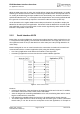
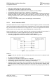
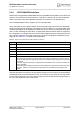
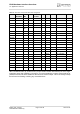
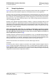
Table Of Contents

EHS6 Hardware Interface Overview
2.1 Application Interface
21
EHS6_HIO_v01.441 Page 14 of 38 2013-07-11
Confidential / Preliminary
The figure below shows a circuit to connect an external SIM card holder.
Figure 5: External UICC/SIM/USIM card holder circuit
The total cable length between the SMT application interface pads on EHS6 and the pads of
the external SIM card holder must not exceed 100mm in order to meet the specifications of
3GPP TS 51.010-1 and to satisfy the requirements of EMC compliance.
To avoid possible cross-talk from the CCCLK signal to the CCIO signal be careful that both
lines are not placed closely next to each other. A useful approach is using a GND line to shield
the CCIO line from the CCCLK line.
2.1.5 Digital Audio Interface
EHS6‘s digital audio interface (DAI) can be used to connect audio devices capable of pulse
code modulation (PCM).
2.1.6 GPIO Interface
EHS6 offers a GPIO interface with 22 GPIO lines. The GPIO lines are shared with other inter-
faces resp. functions: Fast shutdown (see Section 2.1.13), status LED (see Section 2.1.12), the
PWM functionality (see Section 2.1.10), an pulse counter (see Section 2.1.11), ASC0 (see Sec-
tion 2.1.2), ASC1 (see Section 2.1.3), an SPI interface (see Section 2.1.8), an HSIC interface
(see Section 2.1.9) and a PCM interface (see Section 2.1.5)
The following table shows the configuration variants for the GPIO pads. All variants are mutu-
ally exclusive, i.e. a pad configured for instance as Status LED is locked for alternative usage.
SIM
CCVCC
CCRST
CCIO
CCCLK
220nF
1nF
CCIN
V180