EHS6 Version: DocId: 01.441 EHS6_HIO_v01.
EHS6 Hardware Interface Overview 2 Document Name: EHS6 Hardware Interface Overview Version: 01.441 Date: 2013-07-11 DocId: EHS6_HIO_v01.441 Status Confidential / Preliminary GENERAL NOTE THE USE OF THE PRODUCT INCLUDING THE SOFTWARE AND DOCUMENTATION (THE "PRODUCT") IS SUBJECT TO THE RELEASE NOTE PROVIDED TOGETHER WITH PRODUCT. IN ANY EVENT THE PROVISIONS OF THE RELEASE NOTE SHALL PREVAIL. THIS DOCUMENT CONTAINS INFORMATION ON CINTERION PRODUCTS.
EHS6 Hardware Interface Overview Contents 38 Contents 1 Introduction ................................................................................................................. 6 1.1 Key Features at a Glance .................................................................................. 6 1.2 EHS6 System Overview..................................................................................... 9 2 Interface Characteristics ..................................................................
EHS6 Hardware Interface Overview Tables 38 Tables Table 1: Table 2: Table 3: Table 4: Table 5: Table 6: Table 7: Table 8: Table 9: Table 10: Table 11: Table 12: Signals of the SIM interface (SMT application interface) ............................... GPIO lines and possible alternative assignment............................................ Return loss in the active band........................................................................ Overview of operating modes ...................................
EHS6 Hardware Interface Overview Figures 38 Figures Figure 1: Figure 2: Figure 3: Figure 4: Figure 5: Figure 6: Figure 7: Figure 8: Figure 9: EHS6 system overview .................................................................................... 9 USB circuit ..................................................................................................... 10 Serial interface ASC0..................................................................................... 11 Serial interface ASC1.........
EHS6 Hardware Interface Overview 1 Introduction 9 1 Introduction This document1 describes the hardware of the Cinterion EHS6 module. It helps you quickly retrieve interface specifications, electrical and mechanical details and information on the requirements to be considered for integrating further components. 1.
EHS6 Hardware Interface Overview 1.
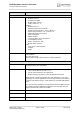
EHS6 Hardware Interface Overview 1.1 Key Features at a Glance 9 Feature Implementation Interfaces Module interface Surface mount device with solderable connection pads (SMT application interface). Land grid array (LGA) technology ensures high solder joint reliability and provides the possibility to use an optional module mounting socket. For more information on how to integrate SMT modules see also [3].
EHS6 Hardware Interface Overview 1.2 EHS6 System Overview 9 Feature Implementation Evaluation kit Evaluation module EHS6 module soldered onto a dedicated PCB that can be connected to an adapter in order to be mounted onto the DSB75. DSB75 DSB75 Development Support Board designed to test and type approve Cinterion Wireless Modules and provide a sample configuration for application engineering. A special adapter is required to connect the EHS6 evaluation module to the DSB75. 1.
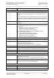
EHS6 Hardware Interface Overview 2 Interface Characteristics 21 2 Interface Characteristics EHS6 is equipped with an SMT application interface that connects to the external application. The SMT application interface incorporates the various application interfaces as well as the RF antenna interface. 2.1 Application Interface 2.1.1 USB Interface EHS6 supports a USB 2.0 High Speed (480Mbit/s) device interface that is Full Speed (12Mbit/ s) compliant.
EHS6 Hardware Interface Overview 2.1 Application Interface 21 While the USB connection is active, the module will not change into SLEEP Mode. To enable switching into SLEEP mode the USB host must bring its USB interface into Suspend state. Also, VUSB_IN should always be kept enabled for this functionality. See “Universal Serial Bus Specification Revision 2.0“1 for a description of the Suspend state.
EHS6 Hardware Interface Overview 2.1 Application Interface 21 • • • • • wake up the application from power saving state. Configured for 8 data bits, no parity and 1 stop bit. ASC0 can be operated at fixed bit rates from 1,200bps up to 921,600bps. Autobauding supports bit rates from 1,200bps up to 230,400bps. Supports RTS0/CTS0 hardware flow control. The hardware hand shake line RTS0 has an internal pull down resistor causing a low level signal, if the line is not used and open.
EHS6 Hardware Interface Overview 2.1 Application Interface 21 2.1.4 UICC/SIM/USIM Interface EHS6 has an integrated UICC/SIM/USIM interface compatible with the 3GPP 31.102 and ETSI 102 221. This is wired to the host interface in order to be connected to an external SIM card holder. Five pads on the SMT application interface are reserved for the SIM interface. The UICC/SIM/USIM interface supports 3V and 1.8V SIM cards.
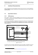
EHS6 Hardware Interface Overview 2.1 Application Interface 21 The figure below shows a circuit to connect an external SIM card holder. V180 CCIN CCVCC SIM 220nF 1nF CCRST CCIO CCCLK Figure 5: External UICC/SIM/USIM card holder circuit The total cable length between the SMT application interface pads on EHS6 and the pads of the external SIM card holder must not exceed 100mm in order to meet the specifications of 3GPP TS 51.010-1 and to satisfy the requirements of EMC compliance.
EHS6 Hardware Interface Overview 2.
EHS6 Hardware Interface Overview 2.1 Application Interface 21 2.1.7 I2C Interface I2C is a serial, 8-bit oriented data transfer bus for bit rates up to 400kbps in Fast mode. It consists of two lines, the serial data line I2CDAT and the serial clock line I2CCLK. The module acts as a single master device, e.g. the clock I2CCLK is driven by the module. I2CDAT is a bi-directional line.
EHS6 Hardware Interface Overview 2.1 Application Interface 21 2.1.10 PWM Interfaces The GPIO6 and GPIO7 interface lines can be configured as Pulse Width Modulation interface lines PWM1 and PWM2. The PWM interface lines can be used, for example, to connect buzzers. The PWM1 line is shared with GPIO7 and the PWM2 line is shared with GPIO6 (for GPIOs see Section 2.1.6). GPIO and PWM functionality are mutually exclusive. 2.1.
EHS6 Hardware Interface Overview 2.2 RF Antenna Interface 21 2.2 RF Antenna Interface The RF interface has an impedance of 50. EHS6 is capable of sustaining a total mismatch at the antenna line without any damage, even when transmitting at maximum RF power. The external antenna must be matched properly to achieve best performance regarding radiated power, modulation accuracy and harmonic suppression.
EHS6 Hardware Interface Overview 2.2 RF Antenna Interface 21 2.2.1 Antenna Installation The antenna is connected by soldering the antenna pad (RF_OUT, i.e., pad #59) and its neighboring ground pads (GND, i.e., pads #58 and #60) directly to the application’s PCB. The antenna pad is the antenna reference point (ARP) for EHS6. All RF data specified throughout this document is related to the ARP.
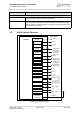
EHS6 Hardware Interface Overview 2.3 Sample Application 21 2.3 Sample Application Figure 6 shows a typical example of how to integrate a EHS6 module with an application. Usage of the various host interfaces depends on the desired features of the application. Because of the very low power consumption design, current flowing from any other source into the module circuit must be avoided, for example reverse current from high state external control lines.
EHS6 Hardware Interface Overview 2.3 Sample Application 21 VDDLP Main Antenna 100k GND IGT RF OUT GND ON EMERG_RST 100k AUTO_ON 0R RESET VDDLP V180 BATT+ 53 VCORE PWR_IND 22k BATT+ 204 Power supply 33pF 100k 150µF, Low ESR! 4.7k EHS6 100k Blocking** Blocking** 4 4 8 3 2 GPIO20...GPIO23/ PCM (DAI) HSIC LPM/ GPIO16...GPIO19/ ASC1/ SPI ASC0 (including GPIO1...
EHS6 Hardware Interface Overview 3 Operating Characteristics 23 3 Operating Characteristics 3.1 Operating Modes The table below briefly summarizes the various operating modes referred to throughout the document. Table 4: Overview of operating modes Mode Function Normal GSM / operation GPRS / UMTS / HSPA SLEEP Power saving set automatically when no call is in progress and the USB connection is suspended by host or not present and no active communication via ASC0.
EHS6 Hardware Interface Overview 3.2 Power Supply 23 3.2 Power Supply EHS6 needs to be connected to a power supply at the SMT application interface (2 lines each BATT+ and GND). The power supply of EHS6 has to be a single voltage source at BATT+. It must be able to provide the peak current during the uplink transmission. All the key functions for supplying power to the device are handled by the power management section of the analog controller.
EHS6 Hardware Interface Overview 4 Mechanical Dimensions, Mounting and Packaging 25 4 Mechanical Dimensions, Mounting and Packaging 4.1 Mechanical Dimensions of EHS6 Figure 7 shows the top and bottom view of EHS6 and provides an overview of the board's mechanical dimensions. For further details see Figure 8. Product label Top view Bottom view Figure 7: EHS6– top and bottom view EHS6_HIO_v01.
EHS6 Hardware Interface Overview 4.1 Mechanical Dimensions of EHS6 25 Figure 8: Dimensions of EHS6 (all dimensions in mm) EHS6_HIO_v01.
EHS6 Hardware Interface Overview 5 Regulatory and Type Approval Information 31 5 Regulatory and Type Approval Information 5.1 Directives and Standards EHS6 is designed to comply with the directives and standards listed below. It is the responsibility of the application manufacturer to ensure compliance of the final product with all provisions of the applicable directives and standards as well as with the technical specifications provided in the "EHS6 Hardware Interface Description".
EHS6 Hardware Interface Overview 5.1 Directives and Standards 31 Table 7: Standards of European type approval ETSI EN 301 489-07 V1.3.1 Electromagnetic Compatibility and Radio spectrum Matters (ERM); Electromagnetic Compatibility (EMC) standard for radio equipment and services; Part 7: Specific conditions for mobile and portable radio and ancillary equipment of digital cellular radio telecommunications systems (GSM and DCS) ETSI EN 301 489-24 V1.5.
EHS6 Hardware Interface Overview 5.1 Directives and Standards 31 Table 10: Toxic or hazardous substances or elements with defined concentration limits EHS6_HIO_v01.
EHS6 Hardware Interface Overview 5.2 SAR requirements specific to portable mobiles 31 5.2 SAR requirements specific to portable mobiles Mobile phones, PDAs or other portable transmitters and receivers incorporating a GSM module must be in accordance with the guidelines for human exposure to radio frequency energy. This requires the Specific Absorption Rate (SAR) of portable EHS6 based applications to be evaluated and approved for compliance with national and/or international regulations.
EHS6 Hardware Interface Overview 5.3 Reference Equipment for Type Approval 31 5.
EHS6 Hardware Interface Overview 5.4 Compliance with FCC and IC Rules and Regulations 31 5.4 Compliance with FCC and IC Rules and Regulations The Equipment Authorization Certification for the Cinterion Wireless Modules reference application described in Section 5.
EHS6 Hardware Interface Overview 6 Document Information 36 6 Document Information 6.1 Revision History New document: "EHS6 Hardware Interface Overview" Version 01.441 Chapter What is new -- Initial document setup. 6.2 [1] [2] [3] Related Documents EHS6 AT Command Set EHS6 Release Note Application Note 48: SMT Module Integration 6.
EHS6 Hardware Interface Overview 6.3 Terms and Abbreviations 36 Abbreviation Description dBm0 Digital level, 3.14dBm0 corresponds to full scale, see ITU G.711, A-law DCE Data Communication Equipment (typically modems, e.g.
EHS6 Hardware Interface Overview 6.
EHS6 Hardware Interface Overview 6.3 Terms and Abbreviations 36 Abbreviation Description SMT Surface Mount Technology SPI Serial Peripheral Interface SRAM Static Random Access Memory TA Terminal adapter (e.g.
EHS6 Hardware Interface Overview 6.4 Safety Precaution Notes 36 6.4 Safety Precaution Notes The following safety precautions must be observed during all phases of the operation, usage, service or repair of any cellular terminal or mobile incorporating EHS6. Manufacturers of the cellular terminal are advised to convey the following safety information to users and operating personnel and to incorporate these guidelines into all manuals supplied with the product.
EHS6 Hardware Interface Overview 7 Appendix 38 7 Appendix 7.
EHS6 Hardware Interface Overview 7.1 List of Parts and Accessories 38 Table 12: Molex sales contacts (subject to change) Molex For further information please click: http://www.molex.com Molex Deutschland GmbH Otto-Hahn-Str. 1b 69190 Walldorf Germany Phone: +49-6227-3091-0 Fax: +49-6227-3091-8100 Email: mxgermany@molex.com American Headquarters Lisle, Illinois 60532 U.S.A. Phone: +1-800-78MOLEX Fax: +1-630-969-1352 Molex China Distributors Beijing, Room 1311, Tower B, COFCO Plaza No.