
User's Manual
Cinterion
®
EHS6-A Hardware Interface Overview Page 14 of 41
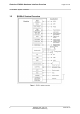
2.1 Application Interface
22
EHS6-A_HIO_v02.770 2014-08-13
Confidential / Preliminary
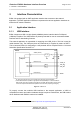
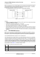
2.1.2 Serial Interface ASC0
EHS6-A offers an 8-wire unbalanced, asynchronous modem interface ASC0 conforming to
ITU-T V.24 protocol DCE signalling. The electrical characteristics do not comply with ITU-T
V.28. The significant levels are 0V (for low data bit or active state) and 1.8V (for high data bit
or inactive state).
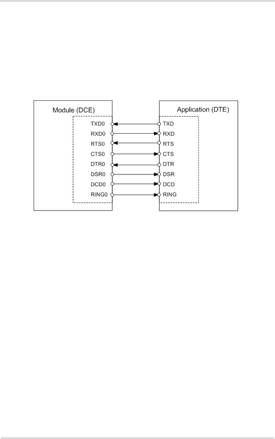
EHS6-A is designed for use as a DCE. Based on the conventions for DCE-DTE connections
it communicates with the customer application (DTE) using the following signals: • Port TXD
@ application sends data to the module’s TXD0 signal line
• Port RXD @ application receives data from the module’s RXD0 signal line
Figure 3: Serial interface ASC0
Features:
• Includes the data lines TXD0 and RXD0, the status lines RTS0 and CTS0 and, in addition,
the modem control lines DTR0, DSR0, DCD0 and RING0.
• ASC0 is designed for controlling GSM/UMTS voice calls, transferring data and for
controlling the module with AT commands.
• Full multiplexing capability allows the interface to be partitioned into virtual channels.
• The RING0 signal serves to indicate incoming calls and other types of URCs (Unsolicited
Result Code). It can also be used to send p ulses to the host application, for example to
wake up the application from power saving state.
• Configured for 8 data bits, no parity and 1 stop bit.
• ASC0 can be operated at fixed bit rates from 1,200bps up to 921,600bps.
• Autobauding supports bit rates from 1,200bps up to 230,400bps.
• Supports RTS0/CTS0 hardware flow control. The hardware hand shake line RTS0 has an
internal pull down resistor causing a low level signal, if t he line is n ot used and open.
Although hardware flow control is recommended, this allows communication by using only
RXD and TXD lines.
• Wake up from SLEEP mode by RTS0 activation (high to low transition).
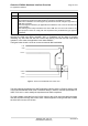
2.1.3 Serial Interface ASC1
Four EHS6-A GPIO lines can be configured as ASC1 interface signals to provide a 4-wire
unbalanced, asynchronous modem interface ASC1 conforming to ITU-T V.24 protocol DCE
signalling. The electrical characteristics do not comply with ITU-T V.28. The significant levels
are 0V (for low data bit or active state) and 1.8V (for high data bit or inactive state).