Cinterion® ALS6A-E Hardware Interface Overview Version: 01.270a DocId: ALS6A-E_HIO_H_v01.270a M2M.GEMALTO.
Cinterion® ALS6A-E Hardware Interface Overview Page 2 of 36 2 Document Name: Cinterion® ALS6A-E Hardware Interface Overview Version: 01.270a Date: 2015-03-10 DocId: ALS6A-E_HIO_H_v01.270a Status Confidential / Released GENERAL NOTE THE USE OF THE PRODUCT INCLUDING THE SOFTWARE AND DOCUMENTATION (THE "PRODUCT") IS SUBJECT TO THE RELEASE NOTE PROVIDED TOGETHER WITH PRODUCT. IN ANY EVENT THE PROVISIONS OF THE RELEASE NOTE SHALL PREVAIL. THIS DOCUMENT CONTAINS INFORMATION ON GEMALTO M2M PRODUCTS.
Cinterion® ALS6A-E Hardware Interface Overview Page 3 of 36 Contents 36 Contents 0 Document History ....................................................................................................... 6 1 Introduction ................................................................................................................. 7 1.1 Supported Products ........................................................................................... 7 1.2 Related Documents ..............................
Cinterion® ALS6A-E Hardware Interface Overview Page 4 of 36 Tables 36 Tables Table 1: Table 2: Table 3: Table 4: Table 5: Table 6: Table 7: Table 8: Table 9: Table 10: Table 11: Table 12: Directives ....................................................................................................... 10 Standards of North American type approval .................................................. 10 Standards of European type approval............................................................
Cinterion® ALS6A-E Hardware Interface Overview Page 5 of 36 Figures 36 Figures Figure 1: Figure 2: Figure 3: Figure 4: Figure 5: Figure 6: Figure 7: ALS6A-E system overview............................................................................. USB circuit ..................................................................................................... UICC/SIM/USIM interface .............................................................................. ALS6A-E – top and bottom view ........
Cinterion® ALS6A-E Hardware Interface Overview Page 6 of 36 0 Document History 6 0 Document History New document: "ALS6A-E Hardware Interface Overview" Version 01.270a Chapter What is new -- Initial document setup. ALS6A-E_HIO_H_v01.
Cinterion® ALS6A-E Hardware Interface Overview Page 7 of 36 1 Introduction 14 1 Introduction The document1 describes the hardware of the Cinterion® ALS6A-E module, designed to connect to a cellular device application and the air interface. It helps you quickly retrieve interface specifications, electrical and mechanical details and information on the requirements to be considered for integrating further components. 1.
Cinterion® ALS6A-E Hardware Interface Overview Page 8 of 36 1.3 Terms and Abbreviations 14 Abbreviation Description EMC Electromagnetic Compatibility ESD Electrostatic Discharge ETS European Telecommunication Standard ETSI European Telecommunications Standards Institute FCC Federal Communications Commission (U.S.
Cinterion® ALS6A-E Hardware Interface Overview Page 9 of 36 1.
Cinterion® ALS6A-E Hardware Interface Overview Page 10 of 36 1.4 Regulatory and Type Approval Information 14 1.4 Regulatory and Type Approval Information 1.4.1 Directives and Standards ALS6A-E has been designed to comply with the directives and standards listed below.
Cinterion® ALS6A-E Hardware Interface Overview Page 11 of 36 1.4 Regulatory and Type Approval Information 14 Table 3: Standards of European type approval EN 301 908-01 V5.2.1 Electromagnetic compatibility and Radio spectrum Matters (ERM); Base Stations (BS) and User Equipment (UE) for IMT-2000 Third Generation cellular networks; Part 1: Harmonized EN for IMT-2000, introduction and common requirements of article 3.2 of the R&TTE Directive EN 301 908-02 V5.2.
Cinterion® ALS6A-E Hardware Interface Overview Page 12 of 36 1.4 Regulatory and Type Approval Information 14 Table 5: Standards of the Ministry of Information Industry of the People’s Republic of China SJ/T 11363-2006 “Requirements for Concentration Limits for Certain Hazardous Substances in Electronic Information Products” (2006-06). SJ/T 11364-2006 “Marking for Control of Pollution Caused by Electronic Information Products” (2006-06).
Cinterion® ALS6A-E Hardware Interface Overview Page 13 of 36 1.4 Regulatory and Type Approval Information 14 1.4.2 SAR requirements specific to portable mobiles Mobile phones, PDAs or other portable transmitters and receivers incorporating a GSM module must be in accordance with the guidelines for human exposure to radio frequency energy.
Cinterion® ALS6A-E Hardware Interface Overview Page 14 of 36 1.4 Regulatory and Type Approval Information 14 1.4.3 SELV Requirements The power supply connected to the ALS6A-E module shall be in compliance with the SELV requirements defined in EN 60950-1. 1.4.4 Safety Precautions The following safety precautions must be observed during all phases of the operation, usage, service or repair of any cellular terminal or mobile incorporating ALS6A-E.
Cinterion® ALS6A-E Hardware Interface Overview Page 15 of 36 2 Product Concept 18 2 Product Concept 2.
Cinterion® ALS6A-E Hardware Interface Overview Page 16 of 36 2.
Cinterion® ALS6A-E Hardware Interface Overview Page 17 of 36 2.1 Key Features at a Glance 18 Feature Implementation Emergency-off Emergency-off by hardware signal EMERG_OFF if IGT is not active Special Features Antenna SAIC (Single Antenna Interference Cancellation) / DARP (Downlink Advanced Receiver Performance) Rx Diversity (receiver type 3i - 64-QAM) / MIMO GPIO 10 I/O pins of the application interface programmable as GPIO. Programming is done via AT commands.
Cinterion® ALS6A-E Hardware Interface Overview Page 18 of 36 2.2 ALS6A-E System Overview 18 2.2 ALS6A-E System Overview GSM/UMTS/LTE Antenna diversity 1 2 Antenna diagnostic Application Antenna switch 2x GPIO GSM/UMTS/LTE 2x ADC Module ADC PCM SIM card Host application Audio codec Power supply UICC Power indication (PWR_IND) GPIO Power for application (VEXT) USB IGT, Emergency Off On/Off Figure 1: ALS6A-E system overview ALS6A-E_HIO_H_v01.
Cinterion® ALS6A-E Hardware Interface Overview Page 19 of 36 3 Application Interface 25 3 Application Interface ALS6A-E is equipped with an SMT application interface (LGA pads) that connects to the external application. The host interface incorporates several sub-interfaces described in the following sections: • • • • • • • Operating modes - see Section 3.1 Power supply - see Section 3.2 Serial interface USB - see Section 3.3 UICC/SIM/USIM interface - see Section 3.
Cinterion® ALS6A-E Hardware Interface Overview Page 20 of 36 3.1 Operating Modes 25 3.1 Operating Modes The table below briefly summarizes the various operating modes referred to in the following chapters. Table 7: Overview of operating modes Mode Function Normal GSM / GPRS / operation UMTS / HSPA / LTE SLEEP Power saving set automatically when no call is in progress and the USB connection is detached.
Cinterion® ALS6A-E Hardware Interface Overview Page 21 of 36 3.2 Power Supply 25 3.2 Power Supply ALS6A-E needs to be connected to a power supply at the SMT application interface - 4 lines BATT+, and GND. There are two separate voltage domains for BATT+: • BATT+_RF with 2 lines for the RF power amplifier supply • BATT+ with 2 lines for the general power management.
Cinterion® ALS6A-E Hardware Interface Overview Page 22 of 36 3.3 USB Interface 25 3.3 USB Interface ALS6A-E supports a USB 2.0 High Speed (480Mbps) device interface. The USB interface is primarily intended for use as command and data interface and for downloading firmware. The USB host is responsible for supplying the VUSB_IN line. This line is for voltage detection only. The USB part (driver and transceiver) is supplied by means of BATT+.
Cinterion® ALS6A-E Hardware Interface Overview Page 23 of 36 3.4 UICC/SIM/USIM Interface 25 3.4 UICC/SIM/USIM Interface ALS6A-E has an integrated UICC/SIM/USIM interface compatible with the 3GPP 31.102 and ETSI 102 221. This is wired to the host interface in order to be connected to an external SIM card holder. Five pads on the SMT application interface are reserved for the SIM interface. The UICC/SIM/USIM interface supports 3V and 1.8V SIM cards.
Cinterion® ALS6A-E Hardware Interface Overview Page 24 of 36 3.4 UICC/SIM/USIM Interface 25 open: Card removed closed: Card inserted Module SMT application interface CCIN CCRST 1n SIM / UICC CCCLK GND CCIO CCVCC 220n Figure 3: UICC/SIM/USIM interface The total cable length between the SMT application interface pads on ALS6A-E and the pads of the external SIM card holder must not exceed 100mm in order to meet the specifications of 3GPP TS 51.010-1 and to satisfy the requirements of EMC compliance.
Cinterion® ALS6A-E Hardware Interface Overview Page 25 of 36 3.5 Pulse Code Modulation Interface (PCM) 25 3.5 Pulse Code Modulation Interface (PCM) ALS6A-E's PCM interface can be used to connect audio devices capable of pulse code modulation. The PCM functionality is limited to the use of wideband codecs with 16kHz sample rate only. 3.6 Analog-to-Digital Converter (ADC) ALS6A-E provides two unbalanced ADC input lines: ADC1_IN and ADC2_IN.
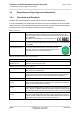
Cinterion® ALS6A-E Hardware Interface Overview Page 26 of 36 4 Antenna Interfaces 27 4 Antenna Interfaces 4.1 GSM/UMTS/LTE Antenna Interface The ALS6A-E GSM/UMTS/LTE antenna interface comprises a GSM/UMTS/LTE main antenna as well as a UMTS/LTE Rx diversity/MIMO antenna to improve signal reliability and quality1. The interface has an impedance of 50. ALS6A-E is capable of sustaining a total mismatch at the antenna interface without any damage, even when transmitting at maximum RF power.
Cinterion® ALS6A-E Hardware Interface Overview Page 27 of 36 4.1 GSM/UMTS/LTE Antenna Interface 27 4.1.1 Antenna Installation The antenna is connected by soldering the antenna pads (ANT_MAIN; ANT_DRX_MIMO) and their neighboring ground pads directly to the application’s PCB. The distance between the antenna pads and their neighboring GND pads has been optimized for best possible impedance. To prevent mismatch, special attention should be paid to these pads on the application’ PCB.
Cinterion® ALS6A-E Hardware Interface Overview Page 28 of 36 5 Mechanics, Mounting and Packaging 29 5 Mechanics, Mounting and Packaging 5.1 Mechanical Dimensions of ALS6A-E Figure 4 shows a 3D view1 of ALS6A-E and provides an overview of the board's mechanical dimensions. For further details see Figure 5. Length: 33mm Width: 29mm Height: 2.2mm Top view Bottom view Figure 4: ALS6A-E – top and bottom view 1. The coloring of the 3D view does not reflect the module’s real color.
Cinterion® ALS6A-E Hardware Interface Overview Page 29 of 36 5.1 Mechanical Dimensions of ALS6A-E 29 Internal use; Not to be soldered Figure 5: Dimensions of ALS6A-E (all dimensions in mm) ALS6A-E_HIO_H_v01.
Cinterion® ALS6A-E Hardware Interface Overview Page 30 of 36 6 Sample Application 31 6 Sample Application Figure 6 shows a typical example of how to integrate an ALS6A-E module with an application. The PWR_IND line is an open collector that needs an external pull-up resistor which connects to the voltage supply VCC µC of the microcontroller. Low state of the open collector pulls the PWR_IND signal low and indicates that the ALS6A-E module is active, high level notifies the Power Down mode.
Cinterion® ALS6A-E Hardware Interface Overview Page 31 of 36 6 Sample Application 31 ALS6A Figure 6: ALS6A-E sample application ALS6A-E_HIO_H_v01.
Cinterion® ALS6A-E Hardware Interface Overview Page 32 of 36 7 Reference Approval 33 7 Reference Approval 7.1 Reference Equipment for Type Approval The Gemalto M2M reference setup submitted to type approve ALS6A-E is shown in Figure 7. The module (i.e., the evaluation module) is connected to the DSB75 by means of a flex cable and a special DSB75 adapter. The GSM/UMTS/LTE test equipment is connected via edge mount SMA connectors soldered to the module’s antenna pads.
Cinterion® ALS6A-E Hardware Interface Overview Page 33 of 36 7.2 Compliance with FCC Rules and Regulations 33 7.2 Compliance with FCC Rules and Regulations The Equipment Authorization Certification for the Gemalto M2M modules reference application described in Section 7.
Cinterion® ALS6A-E Hardware Interface Overview Page 34 of 36 8 Appendix 35 8 Appendix 8.
Cinterion® ALS6A-E Hardware Interface Overview Page 35 of 36 8.1 List of Parts and Accessories 35 Table 11: Molex sales contacts (subject to change) Molex For further information please click: http://www.molex.com Molex Deutschland GmbH Otto-Hahn-Str. 1b 69190 Walldorf Germany Phone: +49-6227-3091-0 Fax: +49-6227-3091-8100 Email: mxgermany@molex.com American Headquarters Lisle, Illinois 60532 U.S.A.
About Gemalto Gemalto (Euronext NL0000400653 GTO) is the world leader in digital security with 2011 annual revenues of €2 billion and more than 10,000 employees operating out of 74 offices and 14 Research & Development centers, located in 43 countries. Gemalto develops secure embedded software and secure products which we design and personalize. Our platforms and services manage these secure products, the confidential data they contain and the trusted end-user services they enable.