
User's Manual
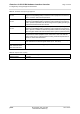
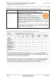
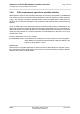
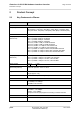
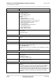
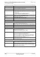
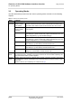
Table Of Contents

Cinterion
®
ALS3-US R4 Hardware Interface Overview
2.1 Key Features at a Glance
18
ALS3-USR4_HIO_v03.915 2017-03-27
Confidential / Preliminary
Page 16 of 44
GSM / GPRS / EGPRS features
Data transfer GPRS:
• Multislot Class 12
• Mobile Station Class B
• Coding Scheme 1 – 4
EGPRS:
• Multislot Class 12
• EDGE E2 power class for 8 PSK
• Downlink coding schemes – CS 1-4, MCS 1-9
• Uplink coding schemes – CS 1-4, MCS 1-9
• SRB loopback and test mode B
• 8-bit, 11-bit RACH
• 1 phase/2 phase access procedures
• Link adaptation and IR
• NACC, extended UL TBF
• Mobile Station Class B
SMS Point-to-point MT and MO
Cell broadcast
Text and PDU mode
Software
AT commands Hayes, 3GPP TS 27.007 and 27.005, and proprietary Gemalto M2M com-
mands
Firmware update Generic update from host application over USB and ASC0
U/SIM application toolkit USAT letter c; with BIP
Audio Audio speech codecs
GSM: WB-AMR, AMR, EFR, FR, HR
3GPP: WB-AMR, AMR
Speakerphone operation, echo cancellation, noise suppression, 9 ringing
tones
VoLTE support for multiple operators, with CSFB
GNSS Features
Protocol NMEA (for GPS, GLONASS and Galileo related sentences)
Modes Standalone GNSS
Assisted GNSS
- Control plane - E911
- User plane - gpsOneXTRA™
General Power saving modes
Power supply for active antenna
Interfaces
Module interface Surface mount device with solderable connection pads (SMT application
interface).
Land grid array (LGA) technology ensures high solder joint reliability and
provides the possibility to use an optional module mounting socket.
For more information on how to integrate SMT modules see also [3]. This
application note comprises chapters on module mounting and application
layout issues as well as on additional SMT application development
equipment.
Feature Implementation