
User's Manual
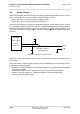
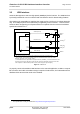
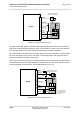
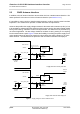
Table Of Contents

Cinterion
®
ALS3-US R3 Hardware Interface Overview
5.2 GNSS Antenna Interface
31
ALS3-USR3_HIO_v03.009 2015-08-05
Confidential / Preliminary
Page 30 of 41
5.2 GNSS Antenna Interface
In addition to the RF antenna interface ALS3-US R3 also has a GNSS antenna interface. The
GNSS pad itself is the same as for the RF antenna interface (see Section 5.1.1).
It is possible to connect active or passive GNSS antennas. In either case they must have 50
impedance. The simultaneous operation of GSM and GNSS is implemented.
ALS3-US R3 provides the supply voltage VGNSS for the GNSS active antenna (3.05V). It has
to be enabled by software when the GNSS receiver becomes active, otherwise VGNSS should
be off (power saving). VGNSS is not short circuit protected. This will have to be provided for by
an external application. The DC voltage should be fed back via ANT_GNSS_DC for coupling
into the GNSS antenna path. Figure 7 shows the flexibility in realizing the power supply for an
active GNSS antenna by giving two sample circuits realizing the supply voltage for an active
GNSS antenna - one with short circuit protection and one with an external LDO employed.
Figure 7: Supply voltage for active GNSS antenna
Short circuit
protection
(Imax=50mA)
VGNSS
ANT_GNSS
Active
GNSS
antenna
10nH
100nF
To GNSS
receiver
Module
SMT interface
ANT_GNSS_DC
typ 3.05V max. 50mA
Not short circuit protected!
1uF
(Optional)
ESD
protection
10k
Supply with short circuit protection
LDO
VGNSS
ANT_GNSS
Active
GNSS
antenna
10nH
100nF
To GNSS
receiver
Module
SMT interface
ANT_GNSS_DC
1uF
(Optional)
ESD
protection
10k
Enable
External
voltage
Supply with external LDO employed