
User's Manual
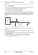
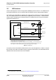
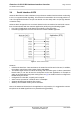
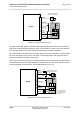
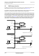
Table Of Contents

Cinterion
®
ALS3-US R3 Hardware Interface Overview
5 Antenna Interfaces
31
ALS3-USR3_HIO_v03.009 2015-08-05
Confidential / Preliminary
Page 28 of 41
5 Antenna Interfaces
5.1 GSM/UMTS/LTE Antenna Interface
The ALS3-US R3 GSM/UMTS/LTE antenna interface comprises a GSM/UMTS/LTE main an-
tenna as well as a UMTS/LTE Rx diversity/MIMO antenna to improve signal reliability and qual-
ity
1
. The interface has an impedance of 50. ALS3-US R3 is capable of sustaining a total
mismatch at the antenna interface without any damage, even when transmitting at maximum
RF power.
The external antennas must be matched properly to achieve best performance regarding radi-
ated power, modulation accuracy and harmonic suppression. Matching networks are not in-
cluded on the ALS3-US R3 PCB and should be placed in the host application, if the antenna
does not have an impedance of 50
.
Regarding the return loss ALS3-US R3 provides the following values in the active band:
1.
By delivery default the UMTS/LTE Rx diversity/MIMO antenna is configured as available for the module
since its usage is mandatory for LTE. Please refer to [1] for details on how to configure antenna settings.
Table 9: Return loss in the active band
State of module Return loss of module Recommended return loss of application
Receive >
8dB > 12dB
Transmit not applicable >
12dB
Idle <
5dB not applicable