
User's Manual
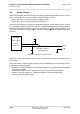
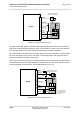
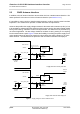
Table Of Contents

Cinterion
®
ALS3-US R3 Hardware Interface Overview
3.2 Power Supply
27
ALS3-USR3_HIO_v03.009 2015-08-05
Confidential / Preliminary
Page 21 of 41
3.2 Power Supply
ALS3-US R3 needs to be connected to a power supply at the SMT application interface - 4 lines
BATT+, and GND. There are two separate voltage domains for BATT+:
• BATT+_RF with 2 lines for the RF power amplifier supply
• BATT+ with 2 lines for the general power management.
The main power supply from an external application has to be a single voltage source and has
to be expanded to two sub paths (star structure). Each voltage domain must be decoupled by
application with low ESR capacitors (
> 47µF MLCC @ BATT+; > 4x47µF MLCC @ BATT+_RF)
as close as possible to LGA pads. Figure 2 shows a sample circuit for decoupling capacitors
for BATT+.
Figure 2: Decoupling capacitor(s) for BATT+
The power supply of ALS3-US R3 must be able to provide the peak current during the uplink
transmission.
All key functions for supplying power to the device are handled by the power management IC.
It provides the following features:
• Stabilizes the supply voltages for the baseband using switching regulators and low drop lin-
ear voltage regulators.
• Switches the module's power voltages for the power-up and -down procedures.
• Delivers, across the VEXT line, a regulated voltage for an external application.
• LDO to provide SIM power supply.
BATT+
2
2
Decoupling capacitors
e.g. 47µF X5R MLCC
4x
GND
BATT+
BATT+_RF
Module
SMT interface
1x