
User's Manual
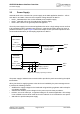
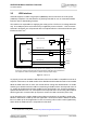
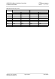
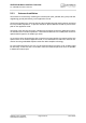
Table Of Contents

AHS3-W Hardware Interface Overview
5 Antenna Interfaces
32
AHS3-W_HIO_v02.540a Page 29 of 41 2012-09-05
Confidential / Preliminary
5 Antenna Interfaces
5.1 GSM/UMTS Antenna Interface
The AHS3-W RF antenna interface comprises a main GSM/UMTS antenna as well as an op-
tional UMTS Rx diversity antenna to improve signal reliability and quality
1
. The RF interface has
an impedance of 50
. AHS3-W is capable of sustaining a total mismatch at the antenna with-
out any damage, even when transmitting at maximum RF power.
The external antenna must be matched properly to achieve best performance regarding radi-
ated power, modulation accuracy and harmonic suppression. Antenna matching networks are
not included on the AHS3-W module and should be placed in the host application.
Regarding the return loss AHS3-W provides the following values in the active band:
1.
By delivery default the optional UMTS Rx diversity antenna is configured as available for the module.
Please refer to [1] for details on how to configure antenna settings.
Table 10: Return loss in the active band
State of module Return loss of module Recommended return loss of application
Receive >
8dB > 12dB
Transmit not applicable >
12dB
Idle <
5dB not applicable