
User's Manual
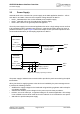
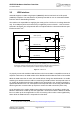
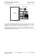
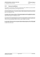
Table Of Contents

AHS3-W Hardware Interface Overview
3.3 USB Interface
28
AHS3-W_HIO_v02.540a Page 22 of 41 2012-09-05
Confidential / Preliminary
3.3 USB Interface
AHS3-W supports a USB 2.0 High Speed (480Mbit/s) device interface that is Full Speed
(12Mbit/s) compliant. The USB interface is primarily intended for use as command and data
interface and for downloading firmware.
The USB host is responsible for supplying the VUSB_IN line. This line is for voltage detection
only. The USB part (driver and transceiver) is supplied by means of BATT+. This is because
AHS3-W is designed as a self-powered device compliant with the “Universal Serial Bus Spec-
ification Revision 2.0”
1
.
Figure 3: USB circuit
To properly connect the module's USB interface to the host a USB 2.0 compatible connector is
required. Furthermore, the USB modem driver distributed with AHS3-W needs to be installed.
While the USB connection is active, the module will not change into SLEEP Mode. To enable
switching into SLEEP mode the USB host must bring its USB interface into Suspend state. Al-
so, VUSB_IN should always be kept enabled for this functionality. See “Universal Serial Bus
Specification Revision 2.0"
1
for a description of the Suspend state. On incoming calls AHS3-W
will then generate a remote wake up request to resume the USB connection (active low).
As an alternative to the regular USB remote wakeup mechanism it is possible to employ the
RING0 or GPIO4 line to wake up the host application. The benefit is that the RING0 or GPIO4
lines can wake up the host application in case of incoming calls or other events signalized by
URCs while the USB interface is suspended or shut down.
1.
The specification is ready for download on http://www.usb.org/developers/docs/
VBUS
DP
DN
VREG (3V075)
BATT+
USB_DP
2)
lin. reg.
GND
Module
Detection only
VUSB_IN
USB part
1)
RING0
Host wakeup
1)
All serial (including R
S
) and pull-up resistors for data lines are implemented.
USB_DN
2)
2)
If the USB interface is operated in High Speed mode (480MHz), it is recommended to take
special care routing the data lines USB_DP and USB_DN. Application layout should in this
case implement a differential impedance of 90Ohm for proper signal integrity.
GPIO4
R
S
R
S
SMT