
User's Manual
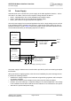
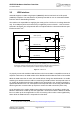
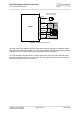
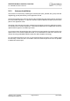
Table Of Contents

AHS3-W Hardware Interface Overview
3.2 Power Supply
28
AHS3-W_HIO_v02.540a Page 21 of 41 2012-09-05
Confidential / Preliminary
3.2 Power Supply
AHS3-W needs to be connected to a power supply at the SMT application interface - 6 lines
each BATT+ and GND. There are three separate voltage domains for BATT+:
• BATT+_WCDMA with 2 lines for the WCDMA power amplifier supply
• BATT+_GSM with 2 lines for the GSM power amplifier supply
• BATT+ with 2 lines for the general power management.
The main power supply from an external application has to be a single voltage source and has
to be expanded to three sub paths (star structure). Capacitors should be placed as close as
possible to the BATT+ pads. Figure 2 shows two sample circuits (minimum requirement and
recommended alternative) for decoupling capacitors for BATT+.
Figure 2: Decoupling capacitor(s) for BATT+
The power supply of AHS3-W must must be able to provide the peak current during the uplink
transmission.
All key functions for supplying power to the device are handled by the power management IC.
It provides the following features:
• Stabilizes the supply voltages for the baseband using switching regulators and low drop lin-
ear voltage regulators.
• Switches the module's power voltages for the power-up and -down procedures.
• Delivers, across the VEXT pin, a regulated voltage for an external application. This voltage
is not available in Power-down mode and can be reduced via AT command to save power.
• SIM switch to provide SIM power supply.
BATT+
BATT+
BATT+_GSM
BATT+_WCDMA
2
2
2
Decoupling capacitor
e.g. 100…220µF
Ultra-low ESR
Module
GND
SMT interface
+
Minimum requirement
BATT+
2
2
2
Decoupling capacitors
e.g. 47µF X5R MLCC
3x
GND
BATT+
BATT+_GSM
BATT+_WCDMA
Module
SMT interface
Recommended alternative