
User's Manual
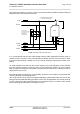
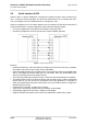
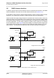
Table Of Contents

Cinterion
®
AGS2-E Hardware Interface Overview
5.1 GSM Antenna Interface
31
AGS2-E_HIO_v00.021 2014-03-20
Confidential / Preliminary
Page 29 of 40
5.1.1 Antenna Installation
The antenna is connected by soldering the antenna pad (ANT_GSM) and their neighboring
ground pads directly to the application’s PCB.
The distance between the antenna pads and their neighboring GND pads has been optimized
for best possible impedance. To prevent mismatch, special attention should be paid to these
pads on the application’ PCB.
The wiring of the antenna connection, starting from the antenna pad to the application’s anten-
na should result in a 50
line impedance. Line width and distance to the GND plane need to
be optimized with regard to the PCB’s layer stack.
To prevent receiver desensitization due to interferences generated by fast transients like high
speed clocks on the external application PCB, it is recommended to realize the antenna con-
nection line using embedded Stripline rather than Micro-Stripline technology.
For type approval purposes, the use of a 50
coaxial antenna connector (U.FL-R-SMT) might
be necessary. In this case the U.FL-R-SMT connector should be placed as close as possible
to AGS2-E‘s antenna pad.