
User's Manual
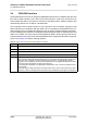
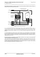
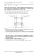
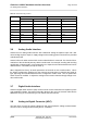
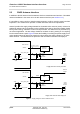
Table Of Contents

Cinterion
®
AGS2-E Hardware Interface Overview
3.9 GPIO Interface
27
AGS2-E_HIO_v00.021 2014-03-20
Confidential / Preliminary
Page 26 of 40
3.9 GPIO Interface
AGS2-E offers a GPIO interface with 4 GPIO lines. The GPIO lines are shared with other inter-
faces, such as the fast shutdown functionality, the PWM functionality, jamming indicator or an-
tenna detection. All functions are controlled by dedicated AT commands.
The following table shows the configuration variants of the GPIO pads. All variants are mutually
exclusive, i.e. a pad configured as GPIO is locked for alternative use.
Each GPIO line can be configured for use as input or output.
3.10 I
2
C Interface
I
2
C is a serial, 8-bit oriented data transfer bus for bit rates up to 400kbps in Fast mode. It con-
sists of two lines, the serial data line I2CDAT and the serial clock line I2CCLK. The module acts
as a single master device, e.g. the clock I2CCLK is driven by the module. I2CDAT is a bi-direc-
tional line. Each device connected to the bus is software addressable by a unique 7-bit ad-
dress, and simple master/slave relationships exist at all times. The module operates as master-
transmitter or as master-receiver. The customer application transmits or receives data only on
request of the module.
3.11 Status LED
One line at the SMT application interface can be configured to drive a status LED which indi-
cates different operating modes of the module.
The STATUS indicator can be enabled/disabled by AT command.
3.12 PWR_IND Signal
The PWR_IND signal notifies the on/off state of the module.
Table 10: GPIO assignment
GPIO FST_SHTDN PWM Jamming indicator Antenna Detection
GPIO4 Yes
GPIO5 Yes
GPIO6 Yes
GPIO7 Yes Yes