
User's Manual
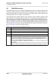
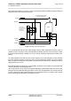
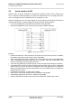
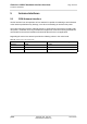
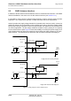
Table Of Contents

Cinterion
®
AGS2-E Hardware Interface Overview
3.6 Analog Audio Interface
27
AGS2-E_HIO_v00.021 2014-03-20
Confidential / Preliminary
Page 25 of 40
3.6 Analog Audio Interface
AGS2-E has an analog audio interface with a balanced analog microphone input and a bal-
anced analog earpiece output. A supply voltage and an analog ground connection are provided
at dedicated pads.
AGS2-E offers six audio modes which can be selected with AT command. The electrical char-
acteristics of the voiceband part vary with the audio mode. For example, sending and receiving
amplification, sidetone paths, noise suppression etc. depend on the selected mode and can be
altered with AT commands (except for mode 1).
When shipped from factory, all audio parameters of AGS2-E are set to audio mode 1. This is
the default configuration optimised for the Votronic HH-SI-30.3/V1.1/0 handset and used for
type approving the Gemalto M2M reference configuration. Audio mode 1 has fix parameters
which cannot be modified. To adjust the settings of the Votronic handset simply change to an-
other audio mode.
3.7 Digital Audio Interface
AGS2-E’s digital audio interface (DAI) can be used to connect audio devices capable of pulse
code modulation (PCM). The PCM functionality allows for the use of an external codec like the
W681360. Using an AT command you can activate the DAI interface.
3.8 Analog-to-Digital Converter (ADC)
The ADC lines are used for antenna diagnosis and general purpose voltage measurements.
The lines can be configured and read by the AT command.
Table 9: DCE-DTE wiring of ASC0
V.24 circuit DCE DTE
Pad function Signal direction Pad function Signal direction
103 TXD0 Input TXD Output
104 RXD0 Output RXD Input
105 RTS0 Input RTS Output
106 CTS0 Output CTS Input
108/2 DTR0 Input DTR Output
107 DSR0 Output DSR Input
109 DCD0 Output DCD Input
125 RING0 Output RING Input