
User's Manual
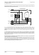
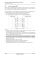
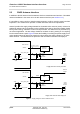
Table Of Contents

Cinterion
®
AGS2-E Hardware Interface Overview
3.5 Serial Interface ASC0
27
AGS2-E_HIO_v00.021 2014-03-20
Confidential / Preliminary
Page 24 of 40
3.5 Serial Interface ASC0
AGS2-E offers an 8-wire unbalanced, asynchronous modem interface ASC0 conforming to
ITU-T V.24 protocol DCE signalling. The electrical characteristics do not comply with ITU-T
V.28. The voltage level of the ASC0 interface is configured to 1.8V.
AGS2-E is designed for use as a DCE. Based on the conventions for DCE-DTE connections it
communicates with the customer application (DTE) using the following signals:
• Port TXD @ application sends data to the module’s TXD0 signal line
• Port RXD @ application receives data from the module’s RXD0 signal line
Figure 3: Serial interface ASC0
Features:
• Includes the data lines TXD0 and RXD0, the status lines RTS0 and CTS0 and, in addition,
the modem control lines DTR0, DSR0, DCD0 and RING0.
• ASC0 is primarily designed for controlling voice calls, transferring CSD, fax and GPRS data
and for controlling the GSM module with AT commands. Also, the GNSS NMEA data
stream is internally routed to the ASC0 interface.
• The DTR0 signal will only be polled once per second from the internal firmware of AGS2-E.
• The RING0 signal serves to indicate incoming calls and other types of URCs (Unsolicited
Result Code). It can also be used to send pulses to the host application, for example to
wake up the application from power saving state. See [1] for details on how to configure the
RING0 line by AT^SCFG.
• Configured for 8 data bits, no parity and 1 stop bit.
• ASC0 can be operated at fixed bit rates from 300bps to 230,400bps.
• Autobauding supports bit rates from 1,200bps to 230,400bps.
• Supports RTS0/CTS0 hardware flow control and XON/XOFF software flow control.