
User's Manual
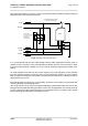
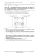
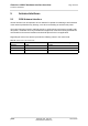
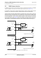
Table Of Contents

Cinterion
®
AGS2-E Hardware Interface Overview
3.4 SIM/USIM Interface
27
AGS2-E_HIO_v00.021 2014-03-20
Confidential / Preliminary
Page 23 of 40
The figure below shows a circuit to connect an external SIM card holder including enhanced
ESD protection for the SIM interface lines.
Figure 2: External SIM card holder circuit
It is recommended that the total cable length between SMT application interface pads on
AGS2-E and the connector of the external SIM card holder must not exceed 100mm in order
to meet the specifications of 3GPP TS 51.010-1 and to satisfy the requirements of EMC com-
pliance.
To avoid possible cross-talk from the CCCLK signal to the CCIO signal be careful that both
lines are not placed closely next to each other. A useful approach would be to use a separate
SIM card ground connection to shield the CCIO line from the CCCLK line. A GND line may be
employed for such a case.
Note: No guarantee can be given, nor any liability accepted, if loss of data is encountered after
removing the SIM card during operation.
Also, no guarantee can be given for properly initialising any SIM card that the user inserts after
having removed a SIM card during operation. In this case, the application must restart AGS2-E.
If using a SIM card holder without detecting contact please be sure to switch off the module
before removing the SIM Card or inserting a new one.
SIM
CCVCC
CCRST
CCIO
CCCLK
100nF
1nF
CCIN
CCIN switch has been closed,
if the SIM card inserted
ESD protection:
5-line transient voltage
supressor array, e.g.,
NUP5120X6 or
ESDA6V1-5P6
51R
51R
51R
51R