
User's Manual
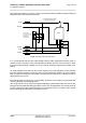
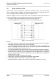
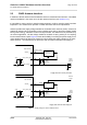
Table Of Contents

Cinterion
®
AGS2-E Hardware Interface Overview
3.2 Power Supply
27
AGS2-E_HIO_v00.021 2014-03-20
Confidential / Preliminary
Page 21 of 40
3.2 Power Supply
AGS2-E needs to be connected to a power supply at the SMT application interface - 4 lines
BATT+, and GND. There are two separate voltage domains for BATT+:
• BATT+ with 2 lines for the general power management.
• BATT+_GSM with 2 lines for the GSM power amplifier supply.
The power supply of AGS2-E has to be a single voltage source at BATT+ and BATT+_GSM. It
must be able to provide the peak current during the uplink transmission.
All the key functions for supplying power to the device are handled by the power management
section of the analog controller. This IC provides the following features:
• Stabilizes the supply voltages for the GSM baseband using low drop linear voltage regula-
tors and a DC-DC step down switching regulator.
• Switches the module's power voltages for the power-up and -down procedures.
• SIM switch to provide SIM power supply.
3.3 RTC Backup
The internal Real Time Clocks of AGS2-E are supplied from a separate voltage regulator in the
power supply component which is also active when AGS2-E is in Power Down mode and
BATT+ is available. In addition, it is possible to backup the RTCs from an external capacitor.