
User's Manual

AC65/AC75 Hardware Interface Description
Confidential / Preliminary
s
AC65/AC75_hd_v00.372 Page 92 of 118 2006-08-03
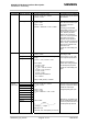
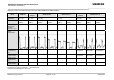
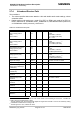
Function Signal name IO Signal form and level Comment
Digital
Analog
Converter
DAC_OUT O V
OL
max = 0.2V at I = 2mA
V
OH
min = 2.55V at I = -0.5mA
V
OH
max = 3.05V
PWM signal which can be
smoothed by an external filter.
Use the AT^SWDAC
command to open and
configure the DAC_OUT
output.
DAI0
O
DAI1
I
DAI2
O
DAI3
O
DAI4
I
DAI5 I
Digital Audio
interface
DAI6 I
V
OL
max = 0.2V at I = 2mA
V
OH
min = 2.55V at I = -0.5mA
V
OH
max = 3.05V
V
IL
max = 0.8V
V
IH
min = 2.15V
V
IH
max = VEXTmin + 0.3V = 3.05V
See Table 16 for details.
If unused keep pins open.
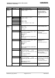
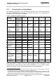
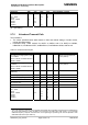
VMIC O V
O
min = 2.4V
V
O
typ = 2.5V
V
O
max = 2.6V
I
max
= 2mA
Microphone supply for
customer feeding circuits
EPP2 O
EPN2 O
3.0Vpp differential typical @ 0dBm0
4.2Vpp differential maximal @ 3.14dBm0
Measurement conditions:
Audio mode: 6
Outstep 3
No load
Minimum differential resp. single ended
load 27Ohms
The audio output can directly
operate a 32-Ohm-
loudspeaker.
If unused keep pins open.
EPP1 O
EPN1 O
4.2Vpp (differential) typical @ 0dBm0
6.0Vpp differential maximal @ 3.14dBm0
Measurement conditions:
Audio mode: 5
Outstep 4
No load
Minimum differential resp. single ended
load 7.5Ohms
The audio output can directly
operate an 8-Ohm-
loudspeaker.
If unused keep pins open.
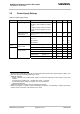
MICP1 I
MICN1 I
Full Scale Input Voltage 1.6Vpp
0dBm0 Input Voltage 1.1Vpp
At MICN1, apply external bias from 1.0V to
1.6V.
Measurement conditions:
Audio mode: 5
Balanced or single ended
microphone or line input with
external feeding circuit (using
VMIC and AGND).
If unused keep pins open.
MICP2 I
MICN2 I
Full Scale Input Voltage 1.6Vpp
0dBm0 Input Voltage 1.1Vpp
At MICN2, apply external bias from 1.0V to
1.6V.
Measurement conditions:
Audio mode: 6
Balanced or single ended
microphone or line input with
external feeding circuit (using
VMIC and AGND).
If unused keep pins open.
Analog
Audio
interface
AGND Analog Ground GND level for external audio
circuits