
User's Manual

AC65/AC75 Hardware Interface Description
Confidential / Preliminary
s
AC65/AC75_hd_v00.372 Page 79 of 118 2006-08-03
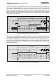
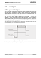
4.1 Antenna Diagnostic
The antenna diagnostic allows the customer to check the presence and the connection
status of the antenna by using the AT^SAD command. A description of the AT^SAD
command can be found in [1].
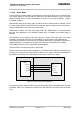
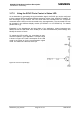
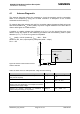
To properly detect the antenna and verify its connection status the antenna feed point must
have a DC resistance R
ANT
of 9kΩ (±3kΩ). Any lower or higher resistance from 1kΩ to 6kΩ or
12kΩ to 40k gives an undefined result.
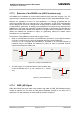
A positive or negative voltage drop (referred to as V
disturb
) on the ground line may occur
without having any impact on the measuring procedure and the measuring result. A peak
deviation (V
disturb
) of ≤ 0.8V from ground is acceptable.
V
disturb
(peak) = ± 0.8V (maximum); f
disturb
= 0Hz … 5kHz
Waveform: DC, sinus, square-pulse, peak-pulse (width = 100µs)
R
disturb
= 5
Figure 38: Resistor measurement used for
antenna detection
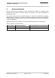
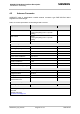
Table 18: Values of the AT^SAD parameter <diag> and their meaning
Antenna connection status indicated by AT^SAD <diag> Equivalent ranges
Normal operation, antenna connected (resistance at
feed point as required)
<diag>=0
R
ANT
= 6kΩ…12kΩ
Antenna connector short-circuited to GND <diag>=1
R
ANT
= 0...1kΩ
Antenna connector is short-circuited to the supply
voltage of the host application, for example the vehicle’s
on-board power supply voltage
<diag>=2 max. 36V
Antenna not properly connected, or resistance at
antenna feed point wrong or not present
<diag>=3
R
ANT
= 40kΩ...Ω
Antenna connector
AC75
9k±3k
External antenna
V
disturb
5 Ohm