
User's Manual

AC65/AC75 Hardware Interface Description
Confidential / Preliminary
s
AC65/AC75_hd_v00.372 Page 76 of 118 2006-08-03
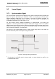
3.17.2 Using the SYNC Pin to Control a Status LED
As an alternative to generating the synchronization signal, the SYNC pin can be configured
to drive a status LED that indicates different operating modes of the AC65/AC75 module. To
take advantage of this function the LED mode must be activated with the AT^SSYNC
command and the LED must be connected to the host application. The connected LED can
be operated in two different display modes (AT^SSYNC=1 or AT^SSYNC=2). For details
please refer to [1].
Especially in the development and test phase of an application, system integrators are
advised to use the LED mode of the SYNC pin in order to evaluate their product design and
identify the source of errors.
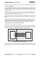
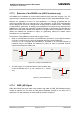
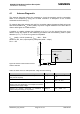
To operate the LED a buffer, e.g. a transistor or gate,
must be included in your application. A sample circuit
is shown in Figure 35. Power consumption in the LED
mode is the same as for the synchronization signal
mode. For details see Table 26, SYNC pin.
Figure 35: LED Circuit (Example)