
User's Manual

AC65/AC75 Hardware Interface Description
Confidential / Preliminary
s
AC65/AC75_hd_v00.372 Page 71 of 118 2006-08-03
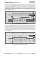
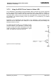
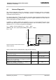
The timing of a PCM short frame is shown in Figure 29. The 16-bit TXDAI and RXDAI data
are transferred simultaneously in both directions during the first 16 clock cycles after the
frame sync pulse. The duration of a frame sync pulse is one BITCLK period, starting at the
rising edge of BITCLK. TXDAI data is shifted out at the next rising edge of BITCLK. RXDAI
data (i.e. data transmitted from the host application to the module’s RXDAI line) is sampled
at the falling edge of BITCLK.
BITCLK
TXDAI
RXDAI
FS
MSB
MSB
LSB
LSB
14 13
14 13
1
1
12
12
2
2
MSB
MSB
125 µs
Figure 29: Master PCM timing, short frame selected
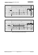
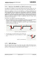
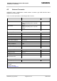
The timing of a PCM
long frame is shown in Figure 30. The 16-bit TXDAI and RXDAI data
are transferred simultaneously in both directions while the frame sync pulse FS is high. For
this reason the duration of a frame sync pulse is 16 BITCLK periods, starting at the rising
edge of BITCLK. TXDAI data is shifted out at the same rising edge of BITCLK. RXDAI data
(i.e. data transmitted from the host application to the module’s RXDAI line) is sampled at the
falling edge of BITCLK.
BITCLK
TXDAI
RXDAI
FS
MSB
MSB
LSB
LSB
14 13
14 13
1
1
12
12
2
2
MSB
MSB
125 µs
Figure 30: Master PCM timing, long frame selected