
User's Manual

AC65/AC75 Hardware Interface Description
Confidential / Preliminary
s
AC65/AC75_hd_v00.372 Page 57 of 118 2006-08-03
3.11 Serial Interface ASC1
The ASC1 interface is available as a 4-wire unbalanced, asynchronous modem interface
ASC1 conforming to ITU-T V.24 protocol DCE signalling. The electrical characteristics do not
comply with ITU-T V.28. The significant levels are 0V (for low data bit or active state) and
2.9V (for high data bit or inactive state). For electrical characteristics please refer to Table
26.
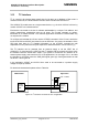
AC65/AC75 is designed for use as a DCE. Based on the conventions for DCE-DTE
connections it communicates with the customer application (DTE) using the following signals:
• Port TXD @ application sends data to module’s TXD1 signal line
• Port RXD @ application receives data from the module’s RXD1 signal line
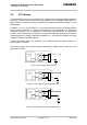
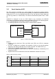
Figure 17: Serial interface ASC1
Features
• Includes only the data lines TXD1 and RXD1 plus RTS1 and CTS1 for hardware
handshake.
• On ASC1 no RING line is available. The indication of URCs on the second interface
depends on the settings made with the AT^SCFG command. For details refer to [1].
• Configured for 8 data bits, no parity and 1 or 2 stop bits.
• ASC1 can be operated at fixed bit rates from 300 bps to 460,800 bps. Autobauding is not
supported on ASC1.
• Supports RTS1/CTS1 hardware flow control and XON/XOFF software flow control.
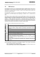
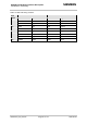
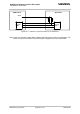
Table 14: DCE-DTE wiring of ASC1
DCE DTE V.24
circuit
Pin function Signal direction Pin function Signal direction
103 TXD1 Input TXD Output
104 RXD1 Output RXD Input
105 RTS1 Input RTS Output
106 CTS1 Output CTS Input
TXD1
RXD1
RTS1
CTS1
TXD
RXD
RTS
CTS
GSM Module (DCE) Application (DTE)