
User manual


5
81505_MHW_450_03-2013_ENG
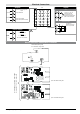
Generic standards, emission standard for residential
commercial and light industrial environments
Emission enclosure
Emission AC mains
Radiated emission
EN 61000-6-3
EN 61000-6-3
EN 61000-6-3
EN 61326 CISPR 16-2
Group1 Class B
Class B
EMC Emission
EMC Immunity
Generic standards, immunity standard for industrial
environments
Immunity ESD
Immunity RF interference
Immunity conducted disturbance
Immunity burst
Immunity pulse
Immunity Magnetic fields
Voltage dips, short interruptions and voltage immunity tests
EN 61000-6-2
EN 61000-4-2
EN 61000-4-3 /A1
EN 61000-4-6
EN 61000-4-4
EN 61000-4-5
EN 61000-4-8
EN 61000-4-11
4 kV contact discharge level 2
8 kV air discharge
level 3
10 V/m amplitude modulated
80 MHz-1 GHz
10 V/m amplitude modulated
1.4 GHz-2 GHz
10 V/m amplitude modulated
0.15 MHz-
80 MHz (level 3)
2 kV power line (level 3)
2 kV I/O signal line (level 4)
Power line-line 1 kV (level 2)
Power line-earth 2 kV (level 3)
Signal line-earth 1 kV (level 2)
100 A/m (level 5)
100%U, 70%U, 40%U,
LVD Safety
Safety requirements for electrical equipment for measurement,
control and laboratory use
EN 61010-1
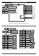
Advice for Correct Installation for EMC
Instrument power supply
• Thepowersupplytotheelectronicequipmentonthe
switchboards must always come directly from an
isolation device with a fuse for the instrument part.
• Theelectronicinstrumentsandelectromechanical
power devices such as relays, contactors, solenoid
valves, etc., must always be powered by separate
lines.
• Whentheelectronicinstrumentpowersupplyis
strongly disturbed by the commutation of transistor or
power units or motors, an isolation transformer
should be used for the controllers only, earthing the
screen.
• Itisessentialthattheplanthasagoodearth
connection:
- the voltage between neutral and earth must not be >1V
-theOhmicresistancemustbe<6Ω;
• Ifthemainsvoltagefluctuatesstrongly,useavoltage
stabilizer.
• Intheproximityofhighfrequencygeneratorsorarc
welders, use adequate mains filters.
• Thepowersupplylinesmustbeseparatefromthe
instrument input and output ones.
Inputs and outputs connection
• Theexternallyconnectedcircuitsmustbedoubly
isolated.
• Toconnecttheanalogueinputsandanalogoutputs
the following is necessary:
- physically separate the input cables from those of the
power supply, the outputs and the power connections.
- use woven and screened cables, with the screen
earthed in one point only.
• Toconnecttherelayoutputs
(contactors, solenoid valves, motors, fans, etc.), fit
RC groups (resistance and condensers in series) in
parallel to the inductive loads that operate in
Alternating Current.
(Note: all the condensers must conform to VDE
(class X2) standards and withstand a voltage of at
least 220V AC. The resistances must be at least 2Ω).
• Fita1N4007diodeinparallelwiththecoilofthe
inductive loads that operate in Direct Current.
GEFRAN S.p.A. declines all responsibility for
any damage to persons or property caused
by tampering, neglect, improper use or any
use which does not conform to the characteristics of
the controller and to the indications given in these
Instructions for Use.