450 CONFIGURABLE CONTROLLER INSTALLATION AND OPERATION MANUAL Software Version 1.
Graphic symbols used To distinguish between the type and importance of the information provided in these instructions for use, graphic symbols have been used as a reference to make interpreting the information clearer. Indicates the contents of the various manual sections, the general warnings, notes, and other points to which the reader’s attention should be drawn.
Preliminary Warnings The following preliminary warnings should be read before installing and using the series 450 controller. This will allow the controller to be put into service more quickly and will avoid certain problems which may mistakenly be interpreted as malfunctions or limitations of the controller.
2 • INSTALLATION AND CONNECTION This section contains the instructions necessary for correct installation of the instrument series 450 into the machine control panel or the host system and for correct connection of the controller power supply, inputs, outputs. Before proceeding with installation read the following warnings carefully! Remember that lack of observation of these warnings could lead to problems of electrical safety and electromagnetic compatibility, as well as invalidating the warranty.
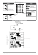
EMC Emission Generic standards, emission standard for residential commercial and light industrial environments Emission enclosure Emission AC mains Radiated emission EN 61000-6-3 EN 61000-6-3 EN 61000-6-3 EN 61326 CISPR 16-2 Group1 Class B Class B EMC Immunity Generic standards, immunity standard for industrial environments Immunity ESD EN 61000-6-2 Immunity RF interference EN 61000-4-3 /A1 Immunity conducted disturbance EN 61000-4-6 Immunity burst EN 61000-4-4 Immunity pulse EN 61000-4-5 Immun
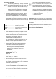
Dimensions and cut-out 63 70 48 48 70 45 45 99 10 Installation with panel mounting As well as the actual instrument and these instructions for use, the controller package also contains: • panel fixing kit (A) • 1 protective seal against dust and water spray (B) A B Fit the instrument to the panel as shown in the figure. Panel B A Warnings and instructions for mounting to the panel Instructions for installation category II, pollution level 2, double isolation.
Electrical Connections TOP • Outputs Out2 (Al) Out1 (Main) + 19 20 Generic user-configurable output - relay 5A/250Vac 21 22 - relay 5A to 250Vac - logic 12Vdc (6Vmin to 20mA) 23 PWR ~ 24 19 18 7 6 20 17 8 5 21 16 9 4 22 15 10 3 23 14 11 2 24 13 12 1 • TC 2 1 ! Standard: 100...240Vac ±10% Available thermocouples: J, K, R, S, T, B, E, N - Respect polarities - For extensions, use compensated cable appropriate for thermocouple.
3 • FUNCTIONS his section describes the use and functions of the displays, lighted indicators and buttons making up the controller operator interface. It therefore contains essential information for correct programming and configuration of the controllers.
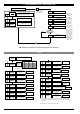
4 • STANDARD CONFIGURATION MENU CFG Setting Parameters Configurat. Default Custom S.tu Autotuning Selftuning Softstart continuous 0 NO NO NO 1 YES NO NO 2 NO YES NO 3 YES YES NO 4 NO NO YES S.tv Enable selftuning, autotuning, softstart 10.0 h.Pb Proportional heating range or hysteresis in regulation ON/OFF 0 ... 999,9% f.s. 4.0 h.It Integral heating time 0,00 ... 99,99 min 1.0 h.dt Derived heating time 0,00 ... 99,99 min 100.0 h.P.X Maximum limit heating power 0,0 ... 100,0% -1 xy.
5 • PROGRAMMING and CONFIGURATION F LEVEL 1 DISPLAY 400 P.V. S.V. Pressed for approx.
• InP InP Input settings Digital filter on main input 0.1 FLt 0.5 FLd 0 dP.S Decimal point position for main input scale 0 Lo.S Minimum limit of main input scale min…max scale of input selected in tyP 1000 XI.s Maximum limit of main input scale min…max scale of input selected in tyP 0 oFS Main input offset correction 0 Lo.L Lower limit for local setpoint and absolute alarms Lo.S ... Hi.S 1000 xI.L Upper limit for local setpoint and absolute alarms Lo.S ... Hi.S 0,0 ...
• Prot Configuraz. Default Custom 64 Pro Protection code Pro 0 1 2 3 Display SP, alarm, OutP SP, alarm, OutP SP SP Change SP, alarm SP SP To activate the turn off SW function, press keys F +4 disables InP, Out +8 disables CFG +16 disables “SW turn on - turn off” +32 disables MAN/AUTO key + 64 to disable manual power memorization F + Δ for 5 secs. in P.V. To return to normal functioning, press key F for 5 secs.
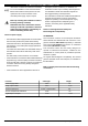
8 • Manual Tuning A) Enter the setpoint at its working value. B) Set the proportional band at 0.1% (with on-off type setting). C) Switch to automatic and observe the behavior of the variable. It will be similar to that in the figure: D) The PID parameters are calculated s follows: Proportional band Process Variable T Peak P.B.= ---------------------------------------- x 100 (V max - V min) Peak Time (V max - V min) is the scale range. Integral time: It = 1.
11 • SELF-TUNING The function works for single output systems (heating or cooling). The self-tuning action calculates optimum control parameter values during process startup. The variable (for example, temperature) must be that assumed at zero power (room temperature). The controller supplies maximum power until an intermediate value between starting value and setpoint is reached, after which it zeros power. PID parameters are calculated by measuring overshoot and the Process time needed to reach peak.
13 • TECHNICAL SPECIFICATIONS Display 2x4 digit green LED’s, digit height 10mm and 7mm Keys 4 mechanical keys (Man/Aut, INC, DEC, F) Accuracy 0.2% f.s. ±1 digit at 25°C ambient temperature Main input TC, RTD (Pt100) Thermocouples IEC 584-1 (J, K, R, S, T, B, E, N) Cold junction error 0,1° / °C RTD type (scale configurable within indicated range, with or without decimal point) Max.
14 • ACCESSORIES • Interface for GEFRAN instrument configuration Kit for PC via the USB port (Windows environment) for GEFRAN instruments configuration: Lets you read or write all of the parameters • A single software for all models • Easy and rapid configuration • Saving and management of parameter recipes • On-line trend and saving of historical data Component Kit: - Connection cable PC USB ... port TTL - Connection cable PC USB ...