
User manual

5
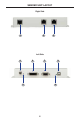
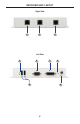
SENDER UNIT DESCRIPTIONS
1 USB Link Connector
Connects the USB signals from the Sender Unit to the Receiver Unit using CAT-
5e / CAT-6 cable.
2 DVI / RS-232 Link Connector
Connects the DVI and RS-232 signals from the Sender Unit to the Receiver Unit
using CAT-5e / CAT-6 cable.
3 Ethernet Input
Connect a CAT-5 cable from a port on a local Ethernet switch to this jack. The
DVIKVM-ELR supports 10/100BaseT Ethernet.
4 5 V DC Locking Power Connector
Connect the included 5 V DC locking power supply to this connector.
5 Power Indicator
This LED will glow red once the included 5V DC locking power supply has
been properly connected to the unit and the locking power supply has been
connected to an available electrical outlet.
6 DVI In
Connect a DVI cable from the computer to this DVI-I connector.
7 RS-232 Port
Connect a RS-232 Serial Cable from the RS-232 host device to this port.
8 USB Indicator
This LED glows green when a USB device is connected to the Sender Unit.
9 USB In
Connects the Sender Unit to the computer using a USB cable.
10 DIP Switches 1 - 2 (on bottom of Unit)
See pages 9 - 11 for details on confi guring the DIP switches.