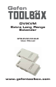
Gefen DVIKVM Extra Long Range Extender GTB-DVIKVM-ELR User Manual www.gefentoolbox.
ASKING FOR ASSISTANCE Technical Support: Telephone (818) 772-9100 Fax (818) 772-9120 Technical Support Hours: 8:00 AM to 5:00 PM Monday thru Friday. Write To: Gefen LLC c/o Customer Service 20600 Nordhoff St Chatsworth, CA 91311 www.gefen.com support@gefen.com Notice Gefen LLC reserves the right to make changes in the hardware, packaging and any accompanying documentation without prior written notice. DVIKVM Extra Long Range Extender is a trademark of Gefen LLC © 2011 Gefen LLC, All Rights Reserved.
CONTENTS 1 Introduction 2 Operation Notes 3 Features 4 Sender Unit Layout 5 Sender Unit Descriptions 6 Receiver Unit Layout 7 Receiver Unit Descriptions 8 Connecting and Operating the DVIKVM Extra Long Range Extender 9 DIP Switch Configuration 12 Firmware Update 13 Network Cable Wiring Diagram 14 Mounting Plate Installation 15 Specifications 16 Warranty
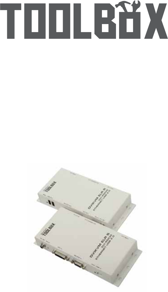
INTRODUCTION Congratulations on your purchase of the GefenToolBox DVIKVM Extra Long Range Extender. Your complete satisfaction is very important to us. About Gefen We specialize in total integration for your home theater, while also focusing on going above and beyond customer expectations to ensure you get the most from your hardware. We invite you to explore our distinct product line. Please visit http://www.gefen.
OPERATION NOTES PLEASE READ THESE NOTES BEFORE INSTALLING OR OPERATING THE DVIKVM EXTRA LONG RANGE EXTENDER • CAT-5 or CAT-6 cables should not exceed 330 feet (100 meters). • Shielded (STP) CAT-5 or CAT-6 is recommended. However, un-shielded (UTP) CAT-5 or CAT-6 is acceptable. NOTE: The shielded cable has an advantage by providing immunity to Electromagnetic Interference (EMI), cell phones and A/C motors.
FEATURES Features • Supports DVI resolutions up to 1920x1200 @ 60 Hz or 1080p at 330 feet (100 meters) • Extends USB 2.0 up to 330 feet (100 meters) • Supports USB 2.0 480 Mbps • Backward-compatible with USB 1.
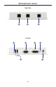
SENDER UNIT LAYOUT Right Side 1 2 3 Left Side 4 6 7 5 9 8 4
SENDER UNIT DESCRIPTIONS 1 USB Link Connector Connects the USB signals from the Sender Unit to the Receiver Unit using CAT5e / CAT-6 cable. 2 DVI / RS-232 Link Connector Connects the DVI and RS-232 signals from the Sender Unit to the Receiver Unit using CAT-5e / CAT-6 cable. 3 Ethernet Input Connect a CAT-5 cable from a port on a local Ethernet switch to this jack. The DVIKVM-ELR supports 10/100BaseT Ethernet.
RECEIVER UNIT LAYOUT Right Side 1 2 3 Left Side 4 6 7 5 8 9 6
RECEIVER UNIT DESCRIPTIONS 1 Remote Ethernet Port Connect a CAT-5 Cable from this jack to the remote device that needs an Ethernet LAN connection. Up to 100BaseT speeds are supported. 2 DVI / RS-232 Link Connector Connects the DVI and RS-232 signals from the Receiver Unit to the Sender Unit using CAT-5e / CAT-6 cable. 3 USB Link Connector Connects the USB signals from the Receiver Unit to the Sender Unit using a second CAT-5e / CAT-6 cable.
CONNECTING AND OPERATING THE DVIKVM EXTRA LONG RANGE EXTENDER How to Connect the DVIKVM Extra Long Range Extender 1. Connect the computer DVI output to the Sender Unit using the provided DVI cable. Connect the monitor to the Receiver Unit using a DVI cable. 2. Connect the included USB cable from the computer to the Sender Unit. 3. Connect the USB devices to the Receiver Unit. 4. Connect the Ethernet port on the Sender Unit to an Ethernet source. 5.
DIP SWITCH CONFIGURATION Sender Unit The Gefen DVIKVM Extra Long Range Extender contains DIP switches on the bottom of the Sender Unit. Each DIP switch performs a different function. Two DIP switches located on the bottom of the Sender Unit. DIP Switch 1 - Power Management (Default = ON) • OFF - Enable Green Mode Sender and Receiver Units are ON only when the DVI source is active. This is the default position.
DIP SWITCH CONFIGURATION Receiver Unit The Gefen DVIKVM Extra Long Range Extender contains four (4) DIP switches on the bottom of the Receiver Unit. Each DIP switch performs a different function. Four DIP switches located on the bottom of the Receiver Unit. DIP Switch 1 - EDID Mode (Default = OFF) • ON - Pass-Through Mode DDC and HPD are passed through. Both the connection status and the full video capabilities of the monitor are used by the source device.
DIP SWITCH CONFIGURATION DIP Switch 2 - Hot Plug Detect (Default = OFF)* • ON - HPD Pass-Through HPD follows upstream HPD towards the source. The HPD signal will reflect the connection status between the display device and the source device. If the source or monitor is temporarily disconnected then reconnected, there will be a delay of 20 - 30 seconds before the content is restored to the monitor. • OFF - HPD Always High The HPD signal remains high regardless of the downstream HPD state.
FIRMWARE UPDATE Updating the Firmware 1. Connect an RS-232 cable from the computer to the Sender Unit. 2. Set DIP switch 2 to the ON position. 3. Connect the 5V DC locking power supply to the Sender Unit. 4. Go to the directory where the firmware files are stored. 5. Double-click the .BAT file. A screen similar to the following will appear: Found sink on port 4 Autodetect platform: full sink Autodetect platform: spi. Autodetect size: 128k Erasing Eeprom....Done. progress: 100% Total bytes: 38804.
NETWORK CABLE WIRING DIAGRAM Gefen recommends the TIA/EIA-568-B wiring option. Please adhere to the table below when field terminating cable for use with Gefen products. Pin Color 1 Orange / White 2 Orange 3 Green / White 4 Blue 5 Blue / White 6 Green 7 Brown / White 8 Brown 12345678 CAT-5, CAT-5e, and CAT-6 cabling comes in stranded and solid core types. Gefen recommends using solid core cabling. It is recommended to use one continuous run from one end to the other.
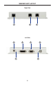
WALL MOUNTING INSTRUCTIONS The GefenToolBox DVIKVM ELR Sender and Receiver may be mounted vertically in a wall or cabinet with wood/drywall screws as shown in the diagram above. There should be an inch or two of clearance between the edges of the unit and any walls or vertical surfaces to allow for enough clearance for insertion and retraction of cables at the DVI and RS-232 connectors. For installation on a drywall surface, use a #6 drywall screw.
SPECIFICATIONS Maximum Pixel Clock................................................................................165 MHz Input Video Signal................................................................................1.2 Volts p-p Input DDC Signal...........................................................................5 Volts p-p (TTL) DVI Connector (Sender / Receiver).........................................DVI-I 29-pin, female USB Connector (Sender)....................................................
WARRANTY Gefen warrants the equipment it manufactures to be free from defects in material and workmanship. If equipment fails because of such defects and Gefen is notified within two (2) years from the date of shipment, Gefen will, at its option, repair or replace the equipment, provided that the equipment has not been subjected to mechanical, electrical, or other abuse or modifications.
Rev A1 20600 Nordhoff St., Chatsworth CA 91311 1-800-545-6900 818-772-9100 www.gefen.com Pb This product uses UL listed power supplies. fax: 818-772-9120 support@gefen.