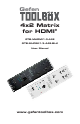
Gefen 4x2 Matrix for HDMI® GTB-MHDMI1.3-442 GTB-MHDMI1.3-442-BLK User Manual www.gefentoolbox.
ASKING FOR ASSISTANCE Technical Support: Telephone Fax (818) 772-9100 (800) 545-6900 (818) 772-9120 Technical Support Hours: 8:00 AM to 5:00 PM Monday thru Friday, Pacific Time Write To: Gefen, LLC. c/o Customer Service 20600 Nordhoff St Chatsworth, CA 91311 www.gefentoolbox.com support@gefentoolbox.com Notice Gefen, LLC reserves the right to make changes in the hardware, packaging and any accompanying documentation without prior written notice.
CONTENTS 1 Introduction 2 Operation Notes 3 Features 4 Panel Layout 5 Panel Descriptions 6 Connecting And Operating The 4x2 Matrix for HDMI 8 IR Remote Description 10 IR Remote Installation 11 IR Remote Configuration 12 Changing the IR Channel 13 IR Extender Installation 14 EDID Management 15 What is EDID? 15 EDID Mode Selection 16 External EDID Management 17 Audio Channel Selection 18 Internal EDID Specification 19 RS-232 Serial Control Interface 20 RS-232 Serial Commands 23 Wall-Moun
INTRODUCTION Congratulations on your purchase of the GefenToolBox 4x2 Matrix for HDMI. Your complete satisfaction is very important to us. About GefenToolBox GefenToolBox is a unique product line offering portable and easy-to-install solutions for common A/V system setups using HDMI. GefenToolBox products are wall-mountable, small in size, and are easily transported to the field, ready for immediate and easy installation in working environments.
OPERATION NOTES READ THESE NOTES BEFORE INSTALLING OR OPERATING THE 4X2 MATRIX FOR HDMI • EDID contains the A/V capabilities of a display device in regards to video resolutions and audio formats supported. This information is used by the source device to determine the format of the A/V signal on the outputs. The GefenToolBox 4x2 Matrix for HDMI incorporates advanced EDID management to ensure complete compatibility with all types of Hi Def sources and HDTV displays. Please see pages 14-18 for more details.
FEATURES HDMI 1.3 Features • • • • 225 MHz (up to 12 bit YUV 444 @ 1080p) Deep Color Dolby TrueHD and DTS-HD Master Audio Lip Sync Features • Displays any of four (4) Hi Def sources on the two (2) HDTV displays, independently. • Maintains beautiful, sharp HDTV resolutions up to 1080p and 2K. • 3DTV Pass-Through • EDID Management for rapid integration of sources and display devices. • Supports digital audio formats including LPCM 7.
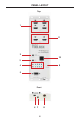
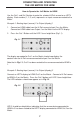
PANEL LAYOUT Top 1 11 2 10 3 9 4 5 Front 8 6 7 4
PANEL DESCRIPTIONS 1 Locking HDMI Input Ports (4) Connect a Hi Def source device to any of these input ports. 2 Audio Channel Selection Switch Modifies the audio information in the EDID when using the Internal EDID mode. See page 17 for more information. 3 EDID Mode Selection Switch Switches between External and Internal EDID. See page 15 for more information. 4 Source Selectors (2) and Indicator LEDs (8) Routes the selected input to a specific display (zone). See page 7 for more information.
CONNECTING AND OPERATING THE 4X2 MATRIX FOR HDMI How to Connect the 4x2 Matrix for HDMI 1. Use the included HDMI cables to connect up to four (4) source devices to the HDMI In ports on the 4x2 Matrix for HDMI. 2. Connect up to two HDTV displays with the supplied HDMI cables. 3. Connect the included 5V DC locking power supply to the power receptacle on the Matrix. Do not overtighten the locking connector. 4. Connect the other end of the power supply to an available power outlet.
CONNECTING AND OPERATING THE 4X2 MATRIX FOR HDMI How to Operate the 4x2 Matrix for HDMI Use the Out 1 and Out 2 button to route the selected Hi Def source to an HDTV display. Each number (1, 2, 3, or 4) represents an input source connected to the Matrix. Example 1: Routing Input (source) 2 to Output (display) 1 1. Connect an HDMI cable from the Hi Def source to Input 2 on the Matrix. Connect an HDMI cable from Output 1 on the Matrix to the HDTV display. 2.
IR REMOTE DESCRIPTION RMT-8MIR Remote 1 2 1 Activity Indicator This LED will be activated momentarily each time a button is pressed. 2 Display and Source Selection Buttons These buttons are used to select which input source is routed to the HDTV display(s). Routing Sources to Displays Issuing a routing command is a simple process. There are a total of 8 buttons on the IR remote. Each set of four (4) buttons are grouped by color for easy navigation.
IR REMOTE DESCRIPTION The IR remote control will allow the user to select which source will be routed to which output. Each of the two (2) outputs are assigned a group of four buttons which correspond to the four source inputs. Please use the information below when selecting the desired source for each display.
IR REMOTE INSTALLATION Installing the IR Remote Battery 1. Remove the battery cover on the back of the remote. 2. Insert the included battery into the open battery slot. The positive (+) side of the battery should be facing up. 3. Make sure that both DIP switches are in the OFF position. 4. Replace the battery cover. The remote ships with 2 batteries. One battery is required for operation and the other battery is a spare.
IR REMOTE CONFIGURATION Setting the IR Remote Channel on the RMT-8MIR In the event that IR commands from other remote controls conflict with the supplied RMT-8MIR Remote, changing the remote IR channel will fix this issue. The RMT-8MIR Remote has a bank of DIP switches for setting the Remote IR channel. The DIP Switch bank on the RMT-8MIR is located underneath the battery cover.
CHANGING THE IR CHANNEL How to change the IR channel Use the following procedure to set the proper IR channel on the 4x2 Matrix for HDMI. 1 Press and hold the Out 1 button for 5 seconds to enter IR channel selection mode. The bank of blue LED indicators will now display the currently selected IR channel. 2 Press the Out 1 button to cycle through each IR channel. The currently selected IR channel will be indicated by a flashing blue LED.
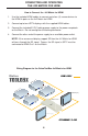
IR EXTENDER INSTALLATION Using the IR Extender An optional IR Extender (Gefen Part No. EXT-RMT-EXTIR) can be used to extend the IR capabilities of the 4x2 Matrix for HDMI. One such application allows the Matrix to be hidden within or behind a cabinet (see illustration below). Simply connect the IR extender to the IR extender port (see page 4).
EDID MANAGEMENT What is EDID? The 4x2 Matrix for HDMI features automatic and manual EDID management to maximize compatibility of all attached devices. First it is necessary to understand EDID and what it is used for. EDID. What is it and what is it used for? Under normal circumstances, source devices will require information about a connected display device to assess what video resolutions and other features are compatible with the output device.
EDID MANAGEMENT EDID Mode Selection 1. EXTERNAL MODE: To use this mode, set the EDID Mode Switch on the front panel to the EXT position. In External EDID mode, the Matrix directly retrieves EDID data from each connected A/V display device and builds a new EDID. This new EDID is sent to the source device.
EXTERNAL EDID MANAGEMENT The 4x2 Matrix for HDMI features EDID Management. Before the source can send video or audio signals to the display, the source devices reads the EDID (Extended Display Identification Data) of each device connected to an output. The EDID contains information about what type of AV data that the source can send to each display. The 4x2 Matrix for HDMI routes multiple source signals to multiple output devices. This involves reading EDID data from more than one device.
EDID MANAGEMENT Audio Channel Selection The 4x2 Matrix for HDMI features a switch that will modify the supported audio formats listed in the pre-programmed EDID. This feature is useful for limiting the output of the source device to either 2 or multi-channel audio formats. NOTE: This selector switch will only affect the pre-programmed EDID in the INTERNAL (INT) EDID Mode. The 4x2 Matrix for HDMI can use either of the following settings for audio format support: 1.
INTERNAL EDID SPECIFICATIONS Below are the settings programmed into the built-in Internal EDID data structure: Video Data Block 1080p@60Hz Audio Data Block Speaker Allocation 2-channel: 2-channel: LPCM 2CH FL/FR Multi-channel: Multi-Channel: LPCM 2CH LPCM 8CH AC-3 6CH DTS 7CH Dolby Digital+ 8CH Dolby TrueHD 8CH DTS-HD 8CH MAT(MLP) 8CH RLC/RRC RL/RR FC LFE FL/FR 1080p@50Hz 1080i@60Hz (native) 1080i@50Hz 18
RS-232 SERIAL CONTROL INTERFACE 54321 12345 9876 6789 Only Pins 2 (RX), 3 (TX), and 5 (Ground) are used on the RS-232 serial interface This feature allows for easy integration into automated systems capable of transmitting RS-232 commands. Please use the settings listed below to configure the RS-232 port of the user’s system. RS-232 Settings Bits per second ................................................................................................. 19200 Data bits ...............................
RS-232 SERIAL CONTROL COMMANDS Commands The following Commands are not case-sensitive Command Description 1,2,3,4,5,6,7,8 Input selection for Output 1 or Output 2 H Reset to factory (default) settings S Returns the current status of the Matrix X Power OFF the Matrix Y Power ON the Matrix 1, 2, 3, 4, 5, 6, 7, 8 Selects the Input to be routed to Output 1 or Output 2. Numbers 1 - 4 route to Output 1. Numbers 5 - 8 route to Output 2.
RS-232 SERIAL CONTROL COMMANDS S Returns the current status of the Matrix. Syntax: S Parameters: None Remarks: When using the S command, the following information is returned: Power state: X (OFF) or Y (ON) Input: 1 - 4 Output: 5 - 8 Examples: The unit is ON and Input 3 is routed to Output 1: S Y35 The Y indicates that the unit is powered ON. The 3 indicates Input 3 and the 5 indicates that the signal is being routed to Output 1.
RS-232 SERIAL CONTROL COMMANDS X Power OFF the Matrix. Syntax: X Parameters: None Y Power ON the Matrix.
WALL MOUNTING INSTRUCTIONS The GefenToolBox 4x2 Matrix for HDMI should be mounted vertically in a wall or cabinet with wood/drywall screws as shown in the diagram above. There should be an inch or two of clearance between the edges of the unit and any walls or vertical surfaces to allow for enough clearance for insertion and retraction of cables at the HDMI connectors. For installation on a drywall surface, use a #6 drywall screw.
SPECIFICATIONS Video Bandwidth ...................................................................................... 225 MHz Pixel Clock / Speed .................................................................................. 165 MHz Maximum Video Resolution ............................. .1080p, 2K with 12-bit Deep Color Input Video Signal .................................................................................... 1.2V p-p Input DDC Signal ........................................................
WARRANTY Gefen warrants the equipment it manufactures to be free from defects in material and workmanship. If equipment fails because of such defects and Gefen is notified within two (2) years from the date of shipment, Gefen will, at its option, repair or replace the equipment, provided that the equipment has not been subjected to mechanical, electrical, or other abuse or modifications.
Rev A8 20600 Nordhoff St., Chatsworth CA 91311 1-800-545-6900 818-772-9100 www.gefentoolbox.com Pb This product uses UL listed power supplies. fax: 818-772-9120 support@gefentoolbox.