1080P 8x8 Matrix for HDMI w/4 ELR-POL Outputs GEF-HDFST-848-4ELR User Manual www.gefenpro.
ASKING FOR ASSISTANCE Technical Support: Telephone Fax (818) 772-9100 (800) 545-6900 (818) 772-9120 Technical Support Hours: 8:00 AM to 5:00 PM Monday thru Friday, Pacific Time Write To: Gefen, LLC. c/o Customer Service 20600 Nordhoff St Chatsworth, CA 91311 www.gefenpro.com support@gefenpro.com Notice Gefen, LLC reserves the right to make changes in the hardware, packaging, and any accompanying documentation without prior written notice.
CONTENTS 1 2 3 4 4 5 6 6 7 8 9 10 10 11 11 12 12 13 13 14 15 18 19 20 22 23 25 27 28 29 30 30 51 60 66 77 78 79 80 Introduction Operation Notes Features Matrix Layout Front Back Matrix Descriptions Front Back ELR-POL Receiver Layout ELR-POL Receiver Descriptions IR Remote Control Layout and Description Installing the Battery Setting the IR Channel Connecting the 8x8 Matrix for HDMI Wiring Diagram Operating the 8x8 Matrix for HDMI Main Display Determining the Current Routing State Routing Sources Locking /
INTRODUCTION Congratulations on your purchase of the GefenPRO 8x8 Matrix for HDMI w/4 ELR Outputs. Your complete satisfaction is very important to us. About Gefen We specialize in total integration for your home theater, while also focusing on going above and beyond customer expectations to ensure you get the most from your hardware. We invite you to explore our distinct product line. Please visit http://www.gefen.
OPERATION NOTES READ THESE NOTES BEFORE INSTALLING OR OPERATING THE 8X8 MATRIX FOR HDMI W/4 ELR-POL OUTPUTS • EDID contains the A/V capabilities of a display device in regards to video resolutions and audio formats supported. This information is used by the source device to determine the format of the A/V signal on the outputs. The 8x8 Matrix for HDMI w/4 ELR-POL Outputs s incorporates advanced EDID management to ensure compatibility with all sources and display devices. See pages 36 for more details.
FEATURES Supported HDMI Features • • • • • • • Resolutions up to 1080p Full HD HDCP compliant 12-bit Deep Color x.v. Color LPCM 7.
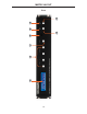
1 2 3 4 6 5 7 8 MATRIX LAYOUT Front 4
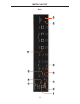
10 11 13 12 14 15 16 17 18 19 MATRIX LAYOUT Back 5
MATRIX DESCRIPTIONS Front 1 LCD Display This is a two-line, sixteen-character display that shows status information and is also used to manage display / source routing. 2 Navigation Buttons (Input / Output) Used for routing and adjusting settings of the 8x8 Matrix for HDMI w/4 ELR-POL Outputs. See the information beginning on page 15 for details on using these buttons. 3 Menu Press this button to display routing, switching mode, and IP address information.
MATRIX DESCRIPTIONS Back 9 IP Control Connect an Ethernet cable to this port to control the 8x8 Matrix for HDMI w/4 ELR-POL Outputss using IP Control. See page 38 for more information on configuring the matrix for IP control. 10 RS-232 Connect an RS-232 cable from this DB-9 connector to the RS-232 control device. See page 28 for more information. 11 Grounding Screw Used to keep electrical current away from circuitry 12 IR EXT Connect an IR extender (Gefen part no.
ELR-POL RECEIVER LAYOUT Top Front 3 1 2 Back 4 8
ELR-POL RECEIVER DESCRIPTIONS Top / Front / Back 1 Power Indicator This LED indicator will glow bright blue when the matrix is powered and the ELR-POL Receiver unit is connected to the matrix using CAT-5e (or better) cable. 2 HDMI Out Connect an HDTV display to the HDMI Out port using an HDMI cable. 3 HDMI Locking Connector Used to lock the HDMI cable in place. 4 ELR-POL In Connect a CAT-5e (or better) cable from this jack to one of the ELR-POL jacks on the 8x8 Matrix for HDMI w/4 ELR-POL Outputs.
IR REMOTE CONTROL Layout and Description (RMT-848IR) 1 2 1 LED Button Press Indicator This LED will be activated momentarily each time a button is pressed. 2 Display and Source Selection Buttons These buttons are used to select which source is routed to a display. The Source and Display buttons are mapped as follows: NOTE: An Activity Indicator that flashes quickly while holding down any one of the 16 buttons indicates a low battery. Replace the IR Remote Control battery as soon as possible.
IR REMOTE CONTROL Installing the Battery The Remote Control unit ships with two batteries (CR2032 lithium battery). One battery is required for operation and the other battery is a spare. 1. Remove the battery cover on the back of the IR Remote Control unit. 2. Insert the included battery into the open battery slot. The positive (+) side of the battery should be facing up. 3. Replace the batteryy cover.
CONNECTING THE 8X8 MATRIX FOR HDMI How to Connect the 8x8 Matrix for HDMI w/4 ELR-POL Outputs 1. Connect up to eight Hi-Def sources to the 8x8 Matrix for HDMI w/4 ELR-POL Outputs s using HDMI cables. 2. Using HDMI cables, connect up to four HDTV displays to the HDMI outputs on the matrix, and up to four HDTV displays to the supplied ELR-POL Receiver units. 3. Connect each ELR-POL Receiver unit to the 8x8 Matrix for HDMI w/4 ELRPOL Outputs s using CAT-5e (or better) cables.
OPERATING THE 8X8 MATRIX FOR HDMI Main Display The Main Display of the 8x8 Matrix for HDMI w/4 ELR-POL Outputss is a 16 character 2 line display. This display shows the current routing status of the matrix and is also used to display additional system information. When the unit is powered on, the following screen is displayed: After a few moments, the status screen is displayed.
OPERATING THE 8X8 MATRIX FOR HDMI Determining the Current Routing State In the example below, the first row (OUT) represents each HDMI output on the matrix. The bottom row (IN) represents each HDMI input on the matrix. Together, these two rows display the current routing state. Starting on the bottom row, we can see that Input 3 has been routed to Outputs A, B, C, and D.
OPERATING THE 8X8 MATRIX FOR HDMI Routing Sources Selecting the Output 1. To select the output, press the Out - or Out + button once. The routing state for Output A will be displayed: 2. Press the Out - or Out + button to cycle through the routing state for each output. Consecutively pressing the Out + button will cycle through each output, from left to right.
OPERATING THE 8X8 MATRIX FOR HDMI 3. Consecutively pressing the Out - button will cycle through each output, from right to left. Changing the Source 4. Once the desired output has been selected, press the Input + or Input button. Consecutively pressing the Input + button will increment the input value by a factor of 1 (within a range of 1 - 8). For example, if Input 4 was originally routed to Output D, then pressing the Input + button will route Input 5 to Output D.
OPERATING THE 8X8 MATRIX FOR HDMI 5. Consecutively pressing the Input - button will decrease the input value by a factor of 1 (within a range of 1 - 8). For example, if Input 3 was originally routed to Output D, pressing the Input - button will route Input 2 to Output D. Source changed from Input p 3 to Input p 2. To change the routing status of another output, press the Output + or Output - buttons to navigate to the desired output.
OPERATING THE 8X8 MATRIX FOR HDMI Locking / Unlocking the Front Panel To prevent an accidental routing change or power-down (by pressing the Power button), the front-panel buttons on the 8x8 Matrix for HDMI w/4 ELR-POL Outputs s can be locked. Locking the matrix also disables many RS-232 / Telnet commands.
OPERATING THE 8X8 MATRIX FOR HDMI FAST SWITCHING TECHNOLOGY Fast Switching Technology Fast Switching Technology (FST) is a Gefen software implementation for HDMI products. FST was created to improve the lengthy HDMI authentication process, based on the HDMI and HDCP specifications. FST provides quicker audio/video source switching and greatly improves the overall audio/video system behavior and performance when more than one HDTV display is used in the system setup.
OPERATING THE 8X8 MATRIX FOR HDMI Determining the Current Switching Mode Each HDMI input can be set to Fast Mode or Slow Mode. It is recommended that each HDMI input be set to Fast Mode for best performance. 1. Consecutively press the Menu button on the front panel until the switching modes screen is displayed. The first row (IN) represents each HDMI input on the matrix. The bottom row (MODE) represents the current switching mode of each HDMI input. Selecting the Input 2.
OPERATING THE 8X8 MATRIX FOR HDMI 3. Press the Output - or Output + button again to cycle through the routing state for each output. Consecutively pressing the Output + button will cycle through each input, from left to right, starting with Input 1: NOTE: In Routing mode, the Output + and Output - buttons cycle through each output. In Switching mode, these same buttons are used to cycle through each input. 4.
OPERATING THE 8X8 MATRIX FOR HDMI Changing the Switching Mode 5. Once the desired input has been selected, press the Input + or Input button to toggle between Fast or Slow switching mode. Switching mode changed from Fast to Slow on Input p 3. To change the switching mode of another input, press the Output + or Output - button to navigate to the desired input. Press the Input + or Input - button to toggle the switching mode between Fast (F) or Slow (S). 6.
OPERATING THE 8X8 MATRIX FOR HDMI Setting the IR Channel on the 8x8 Matrix for HDMI In order for the 8x8 Matrix for HDMII to communicate with the included IR Remote Control, both the matrix and the IR Remote Control must be set to the same IR channel. Follow the procedure outlined below to set the IR channel on the 8x8 Matrix for HDMI. 1. From the Routing screen, simultaneously press the Input -, Input +, and the Output - buttons to display the IR address screen.
OPERATING THE 8X8 MATRIX FOR HDMI 3. After setting the IR address, make sure that the DIP switches on the IR Remote Control are set according to the information in the LCD display. See page 11 for information on setting the IR channel for the IR Remote Control unit. In this case, the 8x8 Matrix for HDMII is set to IR channel 1. Therefore, DIP switch 1 on the IR Remote Control must be set to the ON position and DIP switch 2 must be set to the OFF position. 4.
OPERATING THE 8X8 MATRIX FOR HDMI Routing Sources using the IR Remote Control Buttons 1 - 8 on the IR remote control correspond to each HDMI input (Input 1 - 8) on the Matrix. Buttons A - D correspond to each HDMI output (Output A - D) and buttons E-H correspond to each ELR-POL output (Output E-H). To route a source to a display, press the desired output first, then press the input. Routing Example: Route Input 4 to Output C 1. Select Output C by pressing button C on the IR Remote Control.
OPERATING THE 8X8 MATRIX FOR HDMI 3.
EDID MANAGEMENT External EDID Management The 8x8 Matrix for HDMII features EDID Management. Before the source can send video or audio signals, the source device reads the EDID (Extended Display Identification Data) from the output devices connected to the Splitter. The EDID contains information about what type of audio/video data that the source can send to each output device. The 8x8 Matrix for HDMII routes multiple sources to multiple output devices.
RS-232 SERIAL CONTROL 54321 12345 9876 6789 Only Pins 2 (RX), 3 (TX), and 5 (Ground) are used on the RS-232 serial interface RS232 Settings Bits per second ................................................................................................. 19200 Data bits .................................................................................................................... 8 Parity ..............................................................................................................
IP CONFIGURATION Configuring the IP Address The 8x8 Crosspoint Matrix for HDMII supports IP-based control using Telnet. To set up Telnet control, the network settings for the matrix must be configured via RS-232. The default network settings for the matrix are as follows: IP Address: Subnet: Gateway: HTTP Port: Telnet Port: 192.168.1.72 255.255.255.0 192.168.1.254 80 23 1. Connect an RS-232 cable from the PC to the matrix. 2. Launch a terminal emulation program (e.g.
RS-232 / TELNET COMMANDS IP / Telnet Configuration Command Description #display_telnet_welcome Set Telnet welcome message on login #ipconfig Displays all TCP/IP settings #resetip Resets IP configuration to factory settings #set_http_port Sets the Web server listening port #set_mac_addr Sets the MAC address of the Matrix #set_telnet_pass Prompts for password when using Telnet #set_telnet_port Sets the Telnet listening port #set_telnet_username Sets the user name for the login procedure #se
RS-232 / TELNET COMMANDS #display_telnet_welcome Command The #display_telnet_welcome command sets (enables/disables) the Telnet welcome message on login.
RS-232 / TELNET COMMANDS #ipconfig Command The #ipconfig command displays the current TCP/IP settings for the matrix. Syntax y : #ipconfig Parameters: None Example p : #ipconfig -------------- TCP/IP settings ------------- MAC add = 00:1C:91:01:50:07 IP add = 192.168.1.72 Net Mask = 255.255.255.0 Gateway = 192.168.2.
RS-232 / TELNET COMMANDS #resetip Command The #resetip command resets all TCP/IP settings to factory defaults. Syntax y : #resetip Parameters: None Notes: The matrix must be rebooted after executing this command. Example p : #resetip IP Configuration Was Reset To Factory Defaults. After rebooting the matrix, the IP settings will be cleared. Running the #ipconfig command will display the updated information: #ipconfig IP: 0.0.0.0 SUBNET: 0.0.0.0 GATEWAY: 0.0.0.
RS-232 / TELNET COMMANDS #set_http_port Command The #set_http_port command sets the Web server listening port. The underscore characters (“_”) must be included when typing the command name. The default port setting is 80. Also see the #show_http_port on page 51. Syntax y : #set_http_port param1 Parameters: param1 Port [0 - 65535] Notes: The matrix must be rebooted after executing this command. Example p : #set_http_port 70 HTTP Communication Port 80 Is Set. 34 Please Reboot The Unit.
RS-232 / TELNET COMMANDS #set_mac_addr Command The #set_mac_addr command set the MAC address of the Matrix. The underscore characters (“_”) must be included when typing the command name. The MAC address must be specified using dot-decimal notation. Syntax y : #set_mac_addr param1 Parameters: param1 MAC address Notes: The MAC address should not be changed. This command is for administrator use only. The matrix must be rebooted after executing this command. Example p : #set_mac_addr 00.12.0e.f1.7a.
RS-232 / TELNET COMMANDS #set_telnet_pass Command The #set_telnet_pass command sets the Telnet password. The underscore characters (“_”) must be included when typing the command name. The maximum length of the password is 20 characters. The password is case-sensitive. The default Telnet password is Admin. Syntax y : #set_telnet_pass param1 Parameters: param1 Password Notes: The matrix must be rebooted after executing this command. Example p : #set_telnet_pass OK_Corral TELNET Interface Password Is Set.
RS-232 / TELNET COMMANDS #set_telnet_port Command The #set_telnet_port command sets the Telnet listening port. The underscore characters (“_”) must be included when typing the command name. The default port value is 23. Syntax y : #set_telnet_port param1 Parameters: param1 Port [0 - 65535] Notes: The matrix must be rebooted after executing this command. Example p : #set_telnet_port 20 Telnet Communication Port 23 Is Set. Unit.
RS-232 / TELNET COMMANDS #set_telnet_username Command The #set_telnet_username command sets the Telnet user name. The underscore characters (“_”) must be included when typing the command name. The maximum length of the user name is 8 characters. The user name is case-sensitive. The default Telnet username is Admin. Syntax y : #set_telnet_username param1 Parameters: param1 User name Notes: The matrix must be rebooted after executing this command.
RS-232 / TELNET COMMANDS #set_webui_pass Command The #set_webui_pass command sets the password for the Web interface. The underscore characters (“_”) must be included when typing the command name. The maximum length of the password is 8 characters. Syntax y : #set_webui_pass param1 Parameters: param1 Password Notes: The matrix must be rebooted after executing this command. Example p : #set_webui_pass reindeer Web UI Password Is Set.
RS-232 / TELNET COMMANDS #set_webui_username Command The #set_webui_username command sets the user name for the Web interface. The underscore characters (“_”) must be included when typing the command name. The maximum length of the password is 8 characters. Syntax y : #set_webui_username param1 Parameters: param1 User name Notes: The matrix must be rebooted after executing this command. Example p : #set_webui_username holly_jolly Web UI Password Is Set.
RS-232 / TELNET COMMANDS #sgateway Command The #sgateway sets the IP gateway (router) address. Dot-decimal notation must be used when specifying the IP address. The default Gateway IP address is 192.168.1.254. Syntax y : #sgateway param1 Parameters: param1 IP gateway Notes: The matrix must be rebooted after executing this command. Example: p #sgateway 192.168.2.1 GateWay Address 192.168.2.1 Is Set. Please Reboot The Unit.
RS-232 / TELNET COMMANDS #show_gateway Command The #show_gateway command shows the current gateway address. The underscore characters (“_”) must be included when typing the command name. Syntax y : #show_gateway Parameters: None Example: p #show_gateway GATEWAY ADDRESS IS: 192.168.2.1 #show_http_port Command The #show_http_port command shows the current HTTP listening port. The underscore characters (“_”) must be included when typing the command name.
RS-232 / TELNET COMMANDS #show_ip Command The #show_ip command shows the current IP address of the Matrix. The underscore character (“_”) must be included when typing the command name. Syntax y : #show_ip Parameters: None Example: p #show_ip IP ADDRESS IS: 192.168.1.72 #show_mac_addr Command The #show_mac_addr command shows the MAC address of the Matrix. The underscore characters (“_”) must be included when typing the command name.
RS-232 / TELNET COMMANDS #show_netmask Command The #show_netmask shows the netmask address. The underscore character (“_”) must be included when typing the command name. Syntax y : #show_netmask Parameters: None Example p : #show_netmask NET MASK ADDRESS IS: 255.255.255.0 #show_telnet_port Command The #show_telnet_port command shows the current Telnet listening port.
RS-232 / TELNET COMMANDS #show_telnet_username Command The #show_telnet_username command returns the user name required for login. The underscore characters (“_”) must be included when typing the command name. Syntax y : #show_telnet_username Parameters: None Example p : #show_telnet_username TELNET User Name Doc_Holiday Is Set. #show_ver_data Command The #show_ver_data command displays the hardware and firmware version of the Matrix.
RS-232 / TELNET COMMANDS #show_webui_username Command The #show_webui_username command returns the user name required for login. The underscore characters (“_”) must be included when typing the command name.
RS-232 / TELNET COMMANDS #sipadd Command The #sipadd command sets the IP address of the matrix. Dot-decimal notation must be used when specifying the IP address. Syntax y : #sipadd param1 Parameters: param1 IP address Notes: The matrix must be rebooted after executing this command. Example: p #sipadd 192.168.1.72 IP Address 192.168.2.238 Is Set. Please Reboot The Unit.
RS-232 / TELNET COMMANDS #snetmask Command The #snetmask command sets the IP network subnet mask. Dot-decimal notation must be used when specifying the IP network mask. The default subnet mask is: 255.255.255.0 Syntax y : #snetmask param1 Parameters: param1 Subnet mask Notes: The matrix must be rebooted after executing this command. Syntax y : #snetmask 255.255.0.0 NetMask Address 255.255.255.0 Is Set. Unit.
RS-232 / TELNET COMMANDS #use_telnet_pass Command The #use_telnet_pass command requires or disables Telnet login credentials. The default setting is disabled (param1 = 0). The underscore characters (“_”) must be included when typing the command name.
RS-232 / TELNET COMMANDS #use_webui_pass Command The #use_webui_pass command requires or disables Web UI login credentials. The default setting is disabled (param1 = 0). The underscore characters (“_”) must be included when typing the command name.
RS-232 / TELNET COMMANDS Routing / Naming / Presets Command Description #lock_matrix Locks / unlocks the Matrix #recall_preset Recalls a routing / mask preset #save_preset Saves the current routing/masking state to a preset #set_input_name Specifies a name for an input #set_output_name Specifies a name for an output #show_input_name Displays the specified input name #show_output_name Displays the specified output name #show_r Displays the current routing state of the specified output r Ro
RS-232 / TELNET COMMANDS #lock_matrix Command The #lock_matrix command locks / unlocks the Matrix. When the Matrix is locked, all functions are disabled including the front panel, RS-232, and Telnet. The underscore character (“_”) must be included when typing the command name.
RS-232 / TELNET COMMANDS #recall_preset Command The #recall_preset command recalls a routing preset. Any masked outputs will also be recalled. The underscore character (“_”) must be included when typing the command name. Syntax y : #recall_preset param1 Parameters: param1 Preset [1 - 8] Example p : #recall_preset 1 RECALLED THE ROUTING STATE SAVES TO PRESET 1 #save_preset Command The #save_preset command saves the current routing state to the specified preset.
RS-232 / TELNET COMMANDS #set_input_name Command The #set_input_name command provides a name to the selected input. For example, “Input 1” could be renamed as “DVD_Player”. The maximum string length for param2 2 is 15 characters. Special characters and spaces are not permitted. If needed, use the underscore character (“_”) to separate characters. The underscore character (“_”) must be included when typing the command name.
RS-232 / TELNET COMMANDS #set_output_name Command The #set_output_name command provides a name to the selected output. For example, “Output 1” could be renamed as “HDDisplay”. The maximum string length for param2 2 is 15 characters. Special characters and spaces are not permitted. If needed, use the underscore character (“_”) to separate characters. The underscore character (“_”) must be included when typing the command name.
RS-232 / TELNET COMMANDS #show_input_name Command The #show_input_name command shows the name provided to the specified input using the #set_input_name command. The underscore character (“_”) must be included when typing the command name.
RS-232 / TELNET COMMANDS #show_r Command The #show_r command shows the current routing status of the specified output. The underscore character (“_”) must be included when typing the command name. Syntax y : #show_r param1 Parameters: param1 Output [A - H] Notes: If the output has been renamed using the #set_output_name command, then the name assigned to the output will be included in parentheses.
RS-232 / TELNET COMMANDS r Command The r command routes the specified input to the specified outputs. If param2 2 is set to 0, then the specified input is routed to all outputs. Unlike other commands, do not precede the r command with the “#’ symbol. Syntax y : r param1 param2[...param9] Parameters: param1 Input [1 - 8] param2 Outputs [A - H] Examples: p r 7 A C D F G H INPUT 7 IS SET TO OUTPUTS A, C, D, F, G, H r 2 0 INPUT 2 IS SET TO ALL OUTPUTS.
RS-232 / TELNET COMMANDS s Command The s command routes the specified input to all outputs. Unlike other commands, do not precede the r command with the “#’ symbol. Syntax y : s param1 Parameters: param1 Input [1 - 8] Examples: p s 2 INPUT 2 IS SET TO ALL OUTPUTS.
RS-232 / TELNET COMMANDS Status Command Description #help Displays all available commands #show_fw Displays the Matrix firmware version #show_hpd Displays the HPD status of the specified output #show_rsense Displays the RSENSE status of the specified output m Displays the current matrix routing status in table format n Displays the routing status for the specified output #help Command The #help command displays help on the specified command.
RS-232 / TELNET COMMANDS #show_fw Command The #show_fw command displays the current firmware version of the Matrix. The underscore character (“_”) must be included when typing the command name. Syntax y : #show_fw Parameters: None Example: p #show_fw FIRMWARE VERSION = EXT_HDFST_848CPN v2.
RS-232 / TELNET COMMANDS #show_hdp Command The #show_hpd command displays the HPD (Hot-Plug Detect) status of the specified output. The underscore character (“_”) must be included when typing the command name. Syntax y : #show_hpd param1 Parameters: param1 Output [A - H] Notes: If the output has been renamed using the #set_output_name command, then the name assigned to the output will be included in parentheses.
RS-232 / TELNET COMMANDS #show_rsense Command The #show_rsense command displays Rsense status of the specified output. The underscore character (“_”) must be included when typing the command name. Syntax y : #show_rsense param1 Parameters: param1 Output [A - H] Notes: If the output has been renamed using the #set_output_name command, then the name assigned to the output will be included in parentheses.
RS-232 / TELNET COMMANDS m Command The m command displays the current matrix routing status in table format. Unlike other commands, do not precede the m command with the “#’ symbol.
RS-232 / TELNET COMMANDS n Command The n command displays the current input-output routing state for the specified output. Unlike other commands, do not precede the n command with the “#’ symbol. Syntax y : n param1 Parameters: param1 Output [A - H] Notes: If param1 = 0, then the routing status for all outputs will be displayed.
RS-232 / TELNET COMMANDS Masking Command Description #activeisp Activates ISP mode for firmware updates #echo Enables / disables RS-232 feedback #fadefault Resets the matrix to factory defaults #mask Masks the specified outputs #power Powers the matrix on or off #reboot Reboots the matrix #set_ir Sets the IR channel of the matrix #show_ir Displays the current IR channel of the matrix #show_mask Displays the output masking status #show_out_colordpt Shows the highest color depth supported
RS-232 / TELNET COMMANDS #echo Command The #echo command enables / disables serial port (terminal) echo.
RS-232 / TELNET COMMANDS #fadefault Command The #fadefault command disables the EDID lock state, sets the default routing state (1-1, 2-2, 3-3, etc.), resets the input and output names to the default names (e.g. Output 1, Input 1), and resets the IP configuration to the default settings.
RS-232 / TELNET COMMANDS #mask Command The #mask command masks the specified outputs. If param1 is set to 0, then all outputs are masked. Syntax y : #mask param1[...
RS-232 / TELNET COMMANDS #power Command The #power command toggles the power state on the matrix.
RS-232 / TELNET COMMANDS #reboot Command The #reboot command reboots the matrix. Syntax y : #reboot Parameters: None Example p : #reboot MATRIX WILL REBOOT SHORTLY *REBOOT UNIT IN 2 SECONDS EXT_HDFST_848CPN v2.
RS-232 / TELNET COMMANDS #set_ir Command The #set_ir set the IR channel for the matrix. The associated DIP switch settings for the IR remote control unit are returned. See page 11 for details on setting the IR channel for the IR remote control. The underscore character (“_”) must be included when typing the command name.
RS-232 / TELNET COMMANDS #show_mask Command The #show_mask command shows the mask status for the specified output. The underscore character (“_”) must be included when typing the command name.
RS-232 / TELNET COMMANDS #show_out_colordpt Command The #show_out_colordpt command displays the highest color depth supported by the specified display based on the EDID. The underscore characters (“_”) must be included when typing the command name.
RS-232 / TELNET COMMANDS #show_out_res Command The #show_out_res command displays the highest resolution supported by the specified display based on the EDID.
RS-232 / TELNET COMMANDS #unmask Command The #unmask command unmasks the specified outputs. If param1 is set to 0, then all outputs are unmasked. Syntax y : #unmask param1[...
FIRMWARE UPDATE Firmware Update Procedure The following items are required to update the matrix firmware: • GefenPRO 8x8 Matrix for HDMI w/4 ELR-POL Outputs. • Ethernet cable • Firmware files: GEF-HDFST-848(vXX)(PACK).bin, where vXX = firmware version. 1. Power-on the matrix. 2. Connect the Ethernet cable between the matrix and the computer containing the firmware file. 3. In a Web browser, type in the IP address of the matrix. The following page will be displayed: 4.
RACK MOUNT SAFETY INFORMATION a. Maximum recommended ambient temperature: 40 ˚C (104 ˚F). b. Increase the air flow as needed to maintain the recommended temperature inside the rack. c. Do not exceed maximum weight loads for the rack. Install heavier equipment in the lower part of the rack to maintain stability.
SPECIFICATIONS Maximum Pixel Clock................................................................................225 MHz Video Input Connectors (Matrix)............. (8) HDMI Type A, 19-pin, female, locking Video Output Connectors (Matrix)........................(4) HDMI Type A, 19-pin, female (4) ELR-POL, RJ-45, female Video Input Connector (Receiver)............................................... (1) RJ-45, female Video Output Connector (Receiver).........
WARRANTY Gefen warrants the equipment it manufactures to be free from defects in material and workmanship. If equipment fails because of such defects and Gefen is notified within two (2) years from the date of shipment, Gefen will, at its option, repair or replace the equipment, provided that the equipment has not been subjected to mechanical, electrical, or other abuse or modifications.
*GEF-HDFST-848-4ELR* Rev A1 20600 Nordhoff St., Chatsworth CA 91311 1-800-545-6900 818-772-9100 www.gefenpro.com Pb This product uses UL or CE listed power supplies. fax: 818-772-9120 support@gefenpro.