
User manual


page | 5
Introduction
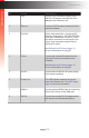
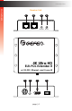
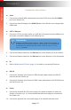
ID Name Description
1 Link Connect a CAT-5e cable (or better), up to
495 feet (150 meters), from this port to the
Link port on the Sender unit.
2 Ethernet Connect a CAT-5e cable (or better) from this
port to the network.
3 IR In/Ext 3.5mm mini-stereo jack. Connect
the included IR extender to this port.
Alternatively, connect a 3.5mm mini-stereo
connector from this port to the output of
an automation system with an electrical IR
output.
See Bidirectional IR Control (page 11)
for more information on using IR.
4 IR Out Connect an IR emitter (Gefen part no. EXT-
IREMIT) from this port to the IR sensor of the
device to be controlled.
See Bidirectional IR Control (page 11)
for more information on using IR.
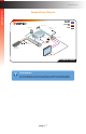
5 24V DC This power receptacle can be used to
connect the included 24V DC power supply.
Only one power supply is required.
The power supply can be connected to
either the Sender or Receiver unit. It is
recommended to connect the power supply
to the Sender unit.
6 Power Link This LED indicator displays the current
state of the Receiver unit. See LED Status
(page 10) for more information.
7 HDMI Out Connect an HDMI cable from this port to an
Ultra-HD display.
8 RS-232 Connect the included RS-232 adapter cable
from this port to the device to be controlled.
Getting Started