*Preferred 4K Ultra HD ELR-POL Extender w/ RS-232, Ethernet and 2-way IR EXT-UHD-CAT5-ELRPOL User Manual Release A1
Important Safety Instructions 1. Read these instructions. 2. Keep these instructions. 3. Heed all warnings. 4. Follow all instructions. 5. Do not use this product near water. 6. Clean only with a dry cloth. 7. Do not block any ventilation openings. Install in accordance with the manufacturer’s instructions. 8. Do not install or place this product near any heat sources such as radiators, heat registers, stoves, or other apparatus (including amplifiers) that produce heat. 9.
Warranty Information Gefen warrants the equipment it manufactures to be free from defects in material and workmanship. If equipment fails because of such defects and Gefen is notified within two (2) years from the date of shipment, Gefen will, at its option, repair or replace the equipment, provided that the equipment has not been subjected to mechanical, electrical, or other abuse or modifications.
Contacting Gefen Technical Support Technical Support (818) 772-9100 (800) 545-6900 8:00 AM to 5:00 PM Monday - Friday, Pacific Time Fax (818) 772-9120 Email support@gefen.com Web http://www.gefen.com Mailing Address Gefen, LLC c/o Customer Service 20600 Nordhoff St. Chatsworth, CA 91311 Product Registration Register your product here: http://www.gefen.com/kvm/Registry/Registration.
Ultra Operating Notes • Gefen recommends using CAT-5e (or better) cables. • Resolution will affect extension distance. 1080p Full HD can be extended up to 495 feet (150 meters) and is limited to 8-bit color depth. 4K resolutions can be extended up to 330 feet (100 meters). See HDBT (HDBaseT™) Mode (page 17) for details. • Power Over Line (POL) is a Gefen proprietary technology that provides power to the Receiver unit over a single CAT-5e (or better) cable.
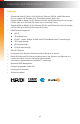
Features and Packing List Features • Extends 4K Ultra HD (3840 x 2160 @ 30 Hz), Ethernet, RS-232, and Bi-Directional IR over a single CAT-5e cable up to 330 feet/100 meters (8-bit color) • Extends HDMI at 1080p Full HD, Ethernet, RS-232, and Bi-Directional IR over a single CAT-5e cable up to 330 feet/100 meters (up to 12-bit Deep Color) • Extends HDMI at 1080p Full HD, Ethernet, RS-232, and Bi-Directional IR over a single CAT-5e cable up to 495 feet/150 meters (8-bit color) • HDMI Features Supported
Features and Packing List Packing List The following items are shipped with the 4K Ultra HD ELR-POL Extender w/ RS-232, Ethernet, and 2-way IR. If any of these items are not present in the box when you first open it, immediately contact your dealer or Gefen. • • • • • • • • • 1 x 4K Ultra HD ELR-POL Extender w/ RS-232, Ethernet, and 2-way IR (Sender unit) 1 x 4K Ultra HD ELR-POL Extender w/ RS-232, Ethernet, and 2-way IR (Receiver unit) 1 x 6 ft.
Table of Contents 1 Getting Started Introduction............................................................................................................ 2 Sender Unit.................................................................................................... 2 Receiver Unit.................................................................................................. 4 Installation..............................................................................................................
4K Ultra HD ELR-POL Extender w/ RS-232, Ethernet and 2-way IR 1 Getting Started Introduction............................................................................................................ 2 Sender Unit.................................................................................................... 2 Receiver Unit.................................................................................................. 4 Installation...................................................................
Introduction Getting Started Sender Unit 1 2 3 4 EXT-UHD-CAT5-ELRPOLS EXT-UHD-CAT5-ELRPOLS EXT-UHD-CAT5-ELRPOLS Link Ethernet IR In/Ext IR Out Link Ethernet IR In/Ext IR Out Link Ethernet IR In/Ext IR Out ® ® ® 4K Ultra HD 4K Ultra HDS ELR-POL Extender ELR-POL 4KExtender Ultra HDIRS w/ RS-232, Ethernet, and 2-way w/ RS-232, Ethernet, and 2-way IR ELR-POL Extender S w/ RS-232, Ethernet, and 2-way IR 5 6 7 8 24V DC Power Link Power 24V DC 24V DC HDMI In RS-232 Link HDMI In RS-232
Getting Started Introduction ID Name Description 1 Link Connect a CAT-5e cable (or better), up to 495 feet (150 meters), from this port to the Link port on the Receiver unit. 2 Ethernet Connect a CAT-5e cable (or better) from this port to the network. 3 IR In/Ext 3.5mm mini-stereo jack. Connect an IR Extender (Gefen part no. EXT-RMT-EXTIRN) to this port. Alternatively, connect a 3.5mm mini-stereo connector from this port to the output of an automation system with an electrical IR output.
Introduction Getting Started Receiver Unit 1 2 3 4 EXT-UHD-CAT5-ELRPOLR EXT-UHD-CAT5-ELRPOLR EXT-UHD-CAT5-ELRPOLR Link Ethernet IR In/Ext IR Out Link Ethernet IR In/Ext IR Out Link Ethernet IR In/Ext IR Out ® ® ® 4K Ultra HD 4K Ultra HDR ELR-POL Extender ELR-POL 4KExtender Ultra HDRIR w/ RS-232, Ethernet, and 2-way w/ RS-232, Ethernet, and 2-way R IR ELR-POL Extender w/ RS-232, Ethernet, and 2-way IR 5 6 7 8 24V DC Power Link Power 24V DC 24V DC HDMI Out RS-232 Link HDMI Out RS
Getting Started Introduction ID Name Description 1 Link Connect a CAT-5e cable (or better), up to 495 feet (150 meters), from this port to the Link port on the Sender unit. 2 Ethernet Connect a CAT-5e cable (or better) from this port to the network. 3 IR In/Ext 3.5mm mini-stereo jack. Connect the included IR extender to this port. Alternatively, connect a 3.5mm mini-stereo connector from this port to the output of an automation system with an electrical IR output.
Getting Started Installation Connection Instructions ►► Video 1. Connect the included HDMI cable between the Ultra Hi-Def source and the HDMI In port on the Sender unit. 2. Connect an Ultra HD display to the HDMI Out port on the Receiver unit using another HDMI cable. ►► CAT-5 / Ethernet 3. Connect a CAT-5e (or better) cable, up to 495 feet (150 meters) from the Link port on the Sender unit and the Link port on the Receiver unit. Information Resolution will affect extension distance.
Installation Getting Started Sample Wiring Diagram CAT-5 CABLE HDMI CABLE RS-232 CABLE IR IN IP Enabled Device IR OUT IR Extender (EXT-RMT-EXTIRN) Gigabit Switch Ultra HD Source Receiver Unit OR IR Emitter OR RS-232 Controlled Device IR Extender (EXT-RMT-EXTIRN) Sender Unit Automation Control Device IR Emitter Ultra HD Display EXT-UHD-CAT5-ELRPOL Information The wiring diagram, shown above, requires an additional IR emitter (Gefen part no. EXT-IREMIT) and IR extender (Gefen part no.
4K Ultra HD ELR-POL Extender w/ RS-232, Ethernet and 2-way IR 2 Basic Operation LED Status........................................................................................................... 10 Bidirectional IR Control.........................................................................................11 Controlling the Source from the Viewing Location....................................... 11 Controlling the Display from the Source Location........................................
Basic Operation LED Status The Power Link LED indicator on the Sender and Receiver unit provides basic information on the current status of the 4K Ultra HD ELR-POL Extender w/ RS-232, Ethernet, and 2-way IR. The information, in the table below, applies to both the Sender and Receiver unit. Status Description Solid blue • The Sender / Receiver unit is powered. • Link integrity between Sender and Receiver unit is good. • Link integrity is compromised.
Basic Operation Bidirectional IR Control Controlling the Source from the Viewing Location 1. Connect the included IR extender to the IR In/Ext port on the Receiver unit. If using an automation system, connect the 3.5mm mini-stereo connector from the IR In/Ext port on the Receiver unit to the automation system. IR signals are transmited over the Link cable. 2. Connect the included IR emitter from the IR Out port, on the Sender unit, to the IR sensor window on the source device.
Basic Operation Bidirectional IR Control Controlling the Display from the Source Location 1. Connect the included IR extender to the IR In/Ext port on the Sender unit. If using an automation system, connect the 3.5mm mini-stereo connector from the IR In/Ext port on the Receiver unit to the automation system. IR signals are transmited over the Link cable. 2. Connect the included IR emitter from the IR Out port on the Receiver unit to the IR sensor on the display.
Basic Operation Bidirectional IR Control Controlling the Source / Display from Different Locations Information Additional IR extenders (Gefen part no. EXT-RMT-EXTIRN) and IR emitters (Gefen part no. EXT-IREMIT) will be required for this configuration. Using bidirectional IR, the 4K Ultra HD ELR-POL Extender w/ RS-232, Ethernet, and 2-way IR allows the source and/or display to be controlled from the Sender or Receiver unit. Refer to the diagram, below, for connection details.
EXT-UHD-CAT5-ELRPOLS Gefen DIP Switch Configuration ETH IR In/Ext IR Out ON SAB Sender unit 1234 ON SAB EXT-UHD-CAT5-ELRPOLR Gefen 1234 Link ETH IR In/Ext IR Out ON 24V DC P/L HDMI In 12 RS-232 Receiver unit Basic Operation Link On the bottom of both the Sender and Receiver unit are a set of DIP switches. The Sender unit has a bank of four DIP switches. The Receiver unit has a bank of two DIP switches. See the following pages for DIP switch settings.
Basic Operation DIP Switch Configuration Each of the following sections describe the DIP switch settings that control each feature. DIP switches that are not related to a specific feature have been grayed-out. Note that DIP switch settings can be used independently or in conjunction with other features, as desired. Information DIP switch 2, on the Receiver unit, is not used and is reserved for optional future expansion.
Basic Operation DIP Switch Configuration HDCP Mode Some source devices (e.g. computers) will always send HDCP. This may cause problems in some systems. Set DIP switch 2, on the Sender unit, to the ON (up) position to ignore detection of an HDCP-compliant display. Otherwise, set DIP switch 2 to the OFF (down) position. Information Setting DIP switch 2 to the ON position (HDCP disabled) does not decrypt HDCP content. Description Sender unit HDCP enabled (default) • ON Enables HDCP pass-through.
Basic Operation DIP Switch Configuration HDBT (HDBaseT™) Mode 1080p Full HD can be extended up to 495 feet (150 meters) and is limited to 8-bit color depth. 4K resolutions can be extended up to 330 feet (100 meters) with deep color. Description Sender unit HDBT mode (default) • ON Allows all resolutions, up to 4K x 2K, to be extended up to 330 feet (100 meters). 1 Long-reach mode • Allows resolutions up to 1080p Full HD to be extended to a maximum distance of 495 feet (150 meters).
4K Ultra HD ELR-POL Extender w/ RS-232, Ethernet and 2-way IR 3 Advanced Operation RS-232 Setup....................................................................................................... 20 Connecting RS-232 Devices........................................................................ 20 Commands...........................................................................................................
U K4 Advanced Operation RS-232 Setup 4K Ultra HD Connecting RS-232 Devices ELR-POL Extender S The 4K Ultra HD ELR-POL Extender w/ RS-232, Ethernet, and 2-way IR supports RS-232 pass-through, allowing the control of RS-232 devices using an automation system. The RS-232 interface is also used to upgrade the firmware and provides a small set of RS-232 commands. See Updating the Firmware (page 28) for details. RS-232, Ethernet, and 2-way IR 1.
Advanced Operation Commands Command Description #fw_upgrade Used to upgrade the firmware #hdcp Enables / disables HDCP detection #help Displays a list of available RS-232 commands #power_always Enables / disables “power always” mode #fw_upgrade Used to upgrade the firmware. See Updating the Firmware (page 28) for information on using this command. Syntax #fw_upgrade param1 Parameters None Example See Updating the Firmware (page 28) for information on using this command.
Advanced Operation Commands #hdcp . Enables / disables HDCP detection on the input. Some computers will enable HDCP if an HDCP-compliant display is detected. Set param1 = 0 to force the computer to ignore detection of an HDCP-compliant display. Information Setting param1 = 0 (HDCP disabled) does not decrypt HDCP content. Syntax #hdcp param1 Parameters param1 Integer [0 ...
Advanced Operation Commands #help The #help command displays the list of available RS-232 commands. Help on a specific command can be displayed when using param1.
Advanced Operation Commands #power_always Sets the power mode. The unit must be rebooted after changing the power mode. Syntax #power_always param1 Parameters param1 Integer [0 ...
4K Ultra HD ELR-POL Extender w/ RS-232, Ethernet and 2-way IR 4 Appendix Updating the Firmware......................................................................................... 28 Single Update Procedure............................................................................. 28 Individual Update Procedure........................................................................ 30 Surface Mounting Instructions..............................................................................
Appendix Updating the Firmware There are two methods for updating the 4K Ultra HD ELR-POL Extender w/ RS-232, Ethernet, and 2-way IR. The recommended method is to update both units at the same time by leaving the Sender and Receiver unit connected. Updating the Sender unit will update the Receiver unit (or vice versa). The second method is to update the Sender and Receiver unit separately.
Appendix Updating the Firmware 7. Assign the following serial port settings in Hyperterminal: Description Setting Baud rate 19200 Data bits 8 Parity None Stop bits 1 Hardware flow control None 8. Reconnect the power supply to the Sender (or Receiver) unit. 9. Type the following in the terminal application: #fw_upgrade 10. Press the [ENTER] key. 11. When prompted, press 1 on the computer keyboard. 12. Click Transfer > Send File... 13. Select the firmware file: ELR_BIDIR_[version].bin. 14.
Appendix Updating the Firmware Individual Update Procedure This method requires that the Sender and Receiver unit are updated separately. Unless there is a specific reason, the Single Update Procedure (page 28) is recommended. 1. Download the latest firmware here: http://www.gefen.com/support/download.jsp 2. Extract the contents of the .zip file to the desktop on your computer. 3. Disconnect the Sender and Receiver unit from the system.
Appendix Updating the Firmware 7. Assign the following serial port settings in Hyperterminal: Description Setting Baud rate 19200 Data bits 8 Parity None Stop bits 1 Hardware flow control None 8. Connect the power supply to the unit. 9. Type the following in the terminal application: #fw_upgrade 10. Press the [ENTER] key. 11. When prompted, press 1 on the computer keyboard. 12. Click Transfer > Send File... 13. Select the firmware file: ELR_BIDIR_[version].bin. 14.
Appendix Surface Mounting Instructions The Sender and Receiver units can be mounted on any flat surface, as shown below (screws not included). There should be an inch or two of clearance between the edges of the unit and any walls or vertical surfaces to allow for enough clearance for connection and disconnection of the HDMI cables. For installation on a drywall surface, use a #6 drywall screw. When installing, it is recommended to use the center hole on a stud.
Appendix Network Cable Diagram Front of RJ-45 Connector 1 2 3 4 5 6 7 8 Gefen recommends the TIA/EIA-568-B wiring option. Use the following table when terminating cables in the field.
Appendix Specifications Supported Formats Video • • • 4K x 2K 1920 x 1200 (WUXGA) 1080p Full HD Audio • • • Linear PCM (7.1 channels) Dolby® TrueHD DTS-HD Master Audio™ HDMI In (Sender) • 1 x HDMI Type A, 19-pin, female HDMI Out (Receiver) • 1 x HDMI Type A, 19-pin, female Link (Sender / Receiver) • 1 x RJ-45, shielded, female Ethernet (Sender / Receiver) • 1 x RJ-45, shielded, female IR In/Ext (Sender / Receiver) • 1 x 3.5mm, female IR Out (Sender / Receiver) • 1 x 3.
Appendix Index Symbols #fw_upgrade 21 #hdcp 22 #help 23 #power_always 24 B Bidirectional IR Control 11 O Operating Notes v P Packing List vi R Receiver Unit 4 RS-232 commands 21 mode 17 RS-232 Setup 20 C Commands 21 #fw_upgrade 21 #hdcp 22 #help 23 #power_always 24 Connection Instructions 6 S Safety Instructions ii Sender Unit 2 Specifications 34 D DIP Switch Configuration 14 T Table of Contents viii Technical Support iv E EDID Management 15 F U Updating the Firmware individual update procedure
*Preferred Stretch it. Switch it. Split it. Gefen’s got it. ® 20600 Nordhoff St., Chatsworth CA 91311 1-800-545-6900 818-772-9100 fax: 818-772-9120 www.gefen.com support@gefen.