® Extender for HDMI® 1.3 over CAT5 with Ethernet EXT-HDMI1.
ASKING FOR ASSISTANCE Technical Support: Telephone Fax (818) 772-9100 (800) 545-6900 (818) 772-9120 Technical Support Hours: 8:00 AM to 5:00 PM Monday thru Friday, Pacific Time Write To: Gefen, LLC. c/o Customer Service 20600 Nordhoff St Chatsworth, CA 91311 www.gefen.com support@gefen.com Notice Gefen, LLC reserves the right to make changes in the hardware, packaging and any accompanying documentation without prior written notice. Extender for HDMI 1.
CONTENTS 1 Introduction 2 Operation Notes 3 Features 4 Sender Unit Layout 5 Sender Panel Descriptions 6 Receiver Panel Layout 7 Receiver Panel Descriptions 8 Connecting the Extender for HDMI 1.
INTRODUCTION Congratulations on your purchase of the Extender for HDMI 1.3 over CAT5 with Ethernet. Your complete satisfaction is very important to us. Gefen Gefen delivers innovative, progressive computer and electronics add-on solutions that harness integration, extension, distribution and conversion technologies.
OPERATION NOTES READ THESE NOTES BEFORE INSTALLING OR OPERATING THE EXTENDER FOR HDMI 1.3 OVER CAT5 WITH ETHERNET • The Extender for HDMI 1.3 over CAT5 with Ethernet units are housed in a metal box for better RF shielding. • CAT-5 cables should not exceed 330 feet. • Shielded CAT-6 with metal RJ-45 connectors are recommended to safeguard against random video flashes caused by electromagnetic interference (EMI). • The Extender for HDMI 1.
FEATURES HDMI 1.3 Features • 225 MHz (up to 12-bit YUV 444 @ 1080p) • Deep Color • Dolby TrueHD and DTS-HD Master Audio • Lip-Sync • CEC Pass-Through Features • Extends HDMI1.
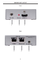
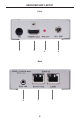
SENDER UNIT LAYOUT Front 1 2 3 Back 4 5 4 6
SENDER UNIT DESCRIPTIONS 1 5V DC Locking Power Connector Connect the included 5V DC locking power supply to this connector. Only use the power supply shipped with this unit. 2 Power Indicator This LED will turn bright red once the included 5V DC locking power supply has been properly connected to the unit and the locking power supply has been connected to an available wall outlet. 3 Locking HDMI Port Connect a 3D Hi-Def source device to this HDMI port.
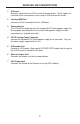
RECEIVER UNIT LAYOUT Front 2 1 3 4 Back 5 6 7 6
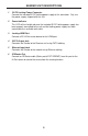
RECEIVER UNIT DESCRIPTIONS 1 IR Sensor Receives signals from the Hi-Def source IR remote control. The IR signals are sent back to the source device, when using an IR Blaster on the Sender. 2 Locking HDMI Port Connect a Hi-Def source device to this HDMI port. 3 Power Indicator This LED will turn bright red once the included 5V DC locking power supply has been properly connected to the unit and the locking power supply has been connected to an available wall outlet.
CONNECTING THE EXTENDER FOR HDMI 1.3 OVER CAT5 WITH ETHERNET 1. Connect the Hi-Def source to the Sender Unit using the included HDMI cable. 2. Use an HDMI cable to connect the HDTV display to the Receiver Unit. 3. Connect the Ethernet device/router to the Ethernet input port on the Sender unit using a CAT-5, CAT-5e or CAT-6 cable. Connect the Ethernet output port on the Receiver Unit to the remote device/router with a CAT-5, CAT-5e or CAT-6 cable. 4.
DIP SWITCHES DIP Switch Location On the bottom of the Extender for HDMI 1.3 with Ethernet Receiver unit there are four (4) DIP switches. The DIP switches allow advanced EDID management of the Extender for HDMI 1.3 with Ethernet which may be necessary when troubleshooting or using different brands of hardware. The DIP switches allow control over the EDID and the HPD (Hot Plug Detect) status. Receiver Unit (bottom) DIP Switch Bank NOTE: DIP switch 4 is not used.
DIP SWITCH SETTINGS DIP 1 - EDID Mode ON (default) - External EDID Mode • DDC and HPD are passed through. Both the connection status and the full A/V capabilities of the display. The HPD status will also be detected by the source device. OFF - Internal EDID Mode • Local EDID is used instead of the EDID from the display device. EDID features newer than HDMI 1.3 are removed when the display is read. This provides a general EDID which is compatible with more displays.
NETWORK CABLE WIRING DIAGRAM Gefen recommends the TIA/EIA-568-B wiring option. Please adhere to the table below when field terminating cable for use with Gefen products. Pin Color 1 Orange / White 2 Orange 3 Green / White 4 Blue 5 Blue / White 6 Green 7 Brown / White 8 Brown 12345678 CAT-5, CAT-5e, and CAT-6 cabling comes in stranded and solid core types. Gefen recommends using solid core cabling. CAT-6 cable is also recommended.
MOUNTING PLATE INSTALLATION 1 Remove the rubber feet covering the screws off the bottom of the unit. Remove the screws. 2 3 Line up the mounting plates and screw it on to the unit.
TERMINOLOGY CAT-5/CAT5e Category 5 cable, commonly known as Cat 5, is an unshielded twisted pair type cable designed for high signal integrity. The actual standard defines specific electrical properties of the wire, but it is mostly known as being rated for its Ethernet capability of 100 Mbit/s. Its specific standard designation is EIA/TIA-568. Cat 5 cable typically has 3 twists per inch of each twisted pair of 24 gauge copper wires within the cable.
SPECIFICATIONS Video Amplifier Bandwidth ....................................................................... 225 MHz Input Video Signal .............................................................................. 1.2 Volts p-p Input DDC Signal ......................................................................... 5 Volts p-p (TTL) Max. Video Resolution Supported ...........................1080p60 / 1920x1200@60 Hz Max. Ethernet Data Transfer Rate.....................................................
13
Rev A10 29.6 20600 Nordhoff St., Chatsworth CA 91311 1-800-545-6900 818-772-9100 www.gefen.com Pb fax: 818-772-9120 support@gefen.