®
ASKING FOR ASSISTANCE Technical Support: Telephone (818) 772-9100 (800) 545-6900 Fax (818) 772-9120 Technical Support Hours: 8:00 AM to 5:00 PM Monday thru Friday. Write To: Gefen LLC c/o Customer Service 20600 Nordhoff St Chatsworth, CA 91311 www.gefen.com support@gefen.com Notice Gefen LLC reserves the right to make changes in the hardware, packaging, and any accompanying documentation without prior written notice.
CONTENTS 1 Introduction 2 Operation Notes 3 Features 4 Sender Unit Layout 5 Sender Unit Descriptions 6 Receiver Unit Layout 7 Receiver Unit Descriptions 8 Connecting the DVIKVM Extra Long Range Extender Over One CAT5 8 9 Wiring Diagram DIP Switch Configuration 11 Network Cable Wiring Diagram 12 Rack Tray Installation 13 Troubleshooting 14 Glossary 21 Specifications 22 Warranty
INTRODUCTION Congratulations on your purchase of the Gefen DVIKVM Extra Long Range Extender Over One CAT5. Your complete satisfaction is very important to us. Gefen Gefen delivers innovative, progressive computer and electronics add-on solutions that harness integration, extension, distribution and conversion technologies.
OPERATION NOTES PLEASE READ THESE NOTES BEFORE INSTALLING OR OPERATING THE DVIKVM EXTRA LONG RANGE EXTENDER OVER ONE CAT5 • Cat-5 or Cat-6 cables should not exceed 330 feet (100 meters). • Shielded (STP) Cat-5 or Cat-6 is recommended. However, un-shielded (UTP) Cat-5 or Cat-6 is acceptable. NOTE: The shielded cable has an advantage by providing immunity to Electromagnetic Interference (EMI), cell phones and A/C motors.
FEATURES Features • Extends DVI and USB 2.0 up to 330 feet (100 meters) over one CAT-5 cable • Supports resolutions up to 1080p and 1920 x 1200 • Supports up to 30 Mbps when using USB 2.0 • Backward-compatible with USB 1.
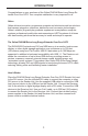
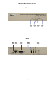
SENDER UNIT LAYOUT Front 1 2 3 8 9 Back 5 6 7 4 4
SENDER UNIT DESCRIPTIONS 1 Power Indicator This LED will turn bright blue once the included 5V DC locking power supply has been properly connected to the unit and the locking power supply has been connected to an available electrical outlet. 2 Link Indicator This LED glows bright blue when the Sender Unit and Receiver Unit are connected using Cat-5 / Cat-6 cable. 3 USB Indicator This LED glows bright blue when a USB source is connected to the Sender Unit.
RECEIVER UNIT LAYOUT Front 1 2 3 Back 5 6 7 8 6 9 4
RECEIVER UNIT DESCRIPTIONS 1 Power Indicator This LED will turn bright blue once the included 5V DC locking power supply has been properly connected to the unit and the locking power supply has been connected to an available electrical outlet. 2 Link Indicator This LED glows bright blue when the Sender Unit and Receiver Unit are connected using Cat-5 / Cat-6 cable. 3 USB Indicator This LED glows bright blue when a USB source is connected to the Receiver Unt.
CONNECTING THE DVIKVM EXTRA LONG RANGE EXTENDER OVER ONE CAT5 How to Connect the DVIKVM Extra Long Range Extender Over One CAT5 1. Connect the DVI source to the Sender Unit using the provided DVI cable. Connect the DVI monitor to the Receiver Unit using a DVI cable. 2. Connect the included USB cable from the computer to the Sender Unit. 3. Connect the USB devices to the Receiver Unit. 4. Connect a Cat-5e or Cat-6 cable between the Link port on the Sender Unit and the Link port on the Receiver Unit.
DIP SWITCH CONFIGURATION Receiver Unit The Gefen DVIKVM Extra Long Range Extender Over One CAT5 contains DIP switches on the bottom of the Receiver Unit (the Sender Unit does not contain any DIP switches). Each DIP switch performs a different function. Two DIP switches located on the bottom of the Receiver Unit. DIP Switch 1 - EDID Management • OFF - Local EDID When Local EDID mode is used, the EDID will be assembled by copying all video and audio features of the connected output device.
DIP SWITCH CONFIGURATION DIP Switch 2* - DVI Support • OFF If an HDMI source is connected, set DIP switch 2 to the OFF position. • ON (default) For DVI connections, set DIP switch 2 to the ON position. DVI is supported by disabling HDCP pass-through. *DIP switch is only functional when DIP switch 1 is set to the OFF position. Once DIP switch changes have been made, the unit must be powercycled for the changes to take effect.
NETWORK CABLE WIRING DIAGRAM Gefen recommends the TIA/EIA-568-B wiring option. Please adhere to the table below when field terminating cable for use with Gefen products. Pin Color 1 Orange / White 2 Orange 3 Green / White 4 Blue 5 Blue / White 6 Green 7 Brown / White 8 Brown 12345678 Cat-5, Cat-5e, and Cat-6 cabling comes in stranded and solid core types. Gefen recommends using solid core cabling. It is recommended to use one continuous run from one end to the other.
RACK TRAY INSTALLATION Step 1 Turn unit upside down. Step 2 Remove rubber feet. Step 3 Line up holes on unit and rack tray. Step 4 Install countersink screws . Step 5 Ensure the unit is installed securely. Step 6 Unit has been installed into rack tray.
TROUBLESHOOTING Cable recommendations Solid core Cat-5e cable rated at 350 MHz and terminated in 568a or 568b is the minimum requirement. For resolutions greater than 1280x1024 or 1080i, Gefen recommends solid shielded Cat-6 cables. No video Make sure that the source is not a dual-link source (resolutions greater than 1920 x 1200). If using a DVI, the source signal must not be HDCP-encrypted. Make sure that DIP switch 2 on the Receiver Unit is set to the ON position.
GLOSSARY A ADC Apple Display Connector. The ADC interface is a proprietary interface developed by Apple that combines analog and digital signals, USB, and power in a single cable. C CAT-5 Category-5 cable, commonly known as Cat-5, is an unshielded twisted pair type cable designed for high signal integrity. The actual standard defines specific electrical properties of the wire, but it is most commonly known as being rated for its Ethernet capability of 100 Mbit/s.
GLOSSARY DDWG An acronym for Digital Display Working Group. DDWG are the creators of the DVI specification. Dolby Digital® This is a digital surround sound technology used in movie theaters and upscale home theater systems that enhances audio. Home theater components with this technology work in conjunction with a “8.1-speaker” system (Eight speakers plus a low-frequency subwoofer) to produce true-to-life audio that draws the listener into the onscreen action.
GLOSSARY F Fiber Optic Refers to the medium and the technology associated with the transmission of information as light pulses along a glass or plastic wire or fiber. Optical fiber carries much more information than conventional copper wire and is in general not subject to electromagnetic interference and the need to retransmit signals. H HDCP High-Bandwidth Digital Content Protection.
GLOSSARY I IEEE 1394a A type of cabling technology for transferring data to and from digital devices at high speed. Some professional digital cameras and memory card readers connect to the computer over FireWire. FireWire card readers are typically faster than those that connect via USB. Also known as IEEE 1394, FireWire was invented by Apple Computer but is now commonly used with Windows-based PCs as well. IR remote A type of wireless transmission using infrared light waves.
GLOSSARY N NTSC NTSC is an acronym for National Television Systems Committee. NTSC is the current analog television standard used in North America, most of South America, Burma, South Korea, Taiwan, Japan, and the Philippines. P PAL An acronym for Phase Alternate Line. PAL is the analog television display standard that is used in Europe and certain other parts of the world. North America uses the NTSC standard. PAL typically uses 625 scan lines, compared to the NTSC standard of 525 scan lines.
GLOSSARY S SDI SDI is the acronym for Serial Digital Interface. SDI is used for standard definition applications (SMPTE 259M) with bit rates of 270 Mb/s, 360 Mb/s, 143 Mb/s, and 177 Mb/s. 270 Mb/s is the most common. Bit rates below 270 Mb/s were designed for the digital transmission of composite (NTSC or PAL) video. SMPTE The acronym for Society of Motion Picture and Television Engineers. SMPTE was founded in 1916 and is an international professional association, based in the U.S.
GLOSSARY U USB USB is an acronym for Universal Serial Bus. USB can connect computer peripherals such as mice, keyboards, digital cameras, printers, personal media players, flash drives, Network Adapters, and external hard drives. For the most part, USB has made interfaces such as serial and parallel ports obsolete. V VESA VESA (Video Electronics Standards Association) is an international standards entity for computer graphics.
SPECIFICATIONS Maximum Pixel Clock................................................................................165 MHz Maximum TMDS Clock..............................................................................165 MHz Video Input Connector (Sender).....................(1) DVI-I 29-pin, female (digital only) Video Output Connector (Receiver)...............(1) DVI-I 29-pin, female (digital only) USB Host Connector (Sender)...........................................
WARRANTY Gefen warrants the equipment it manufactures to be free from defects in material and workmanship. If equipment fails because of such defects and Gefen is notified within two (2) years from the date of shipment, Gefen will, at its option, repair or replace the equipment, provided that the equipment has not been subjected to mechanical, electrical, or other abuse or modifications.
Rev A5 Pb This product uses UL listed or CE compliant power supplies.