EXT-DVIKVM-241DL User Manual www.gefen.
ASKING FOR ASSISTANCE Technical Support: Telephone Fax (818) 772-9100 (800) 545-6900 (818) 772-9120 Technical Support Hours: 8:00 AM to 5:00 PM Monday thru Friday. Write To: Gefen LLC c/o Customer Service 20600 Nordhoff St Chatsworth, CA 91311 www.gefen.com support@gefen.com Notice Gefen LLC reserves the right to make changes in the hardware, packaging, and any accompanying documentation without prior written notice. 2x1 DVIKVM DL Switch is a trademark of Gefen LLC © 2011 Gefen, LLC.
CONTENTS 1 Introduction 2 Operation Notes 3 Features 4 Panel Layout 5 Panel Descriptions 6 IR Remote Control 6 Layout and Descriptions 7 Installing the Battery 7 Setting the IR channel 8 8 9 Connecting the 2x1 DVIKVM DL Switch Wiring Diagram Operating the 2x1 DVIKVM DL Switch 9 Switching sources 9 Switching using the IR Remote Control 10 Switching using the RMT2 11 Switching using contact closure 12 Setting the IR channel 13 Using the IR Extender 14 Specifications 15 Warranty
INTRODUCTION Congratulations on your purchase of the Gefen 2X1 DVIKVM DL Switch. Your complete satisfaction is very important to us. Gefen Gefen delivers innovative, progressive computer and electronics add-on solutions that harness integration, extension, distribution and conversion technologies.
OPERATION NOTES PLEASE READ THESE NOTES BEFORE INSTALLING OR OPERATING THE 2X1 DVIKVM DL SWITCH • When turning on or rebooting your computers, the DVI DL Switcher must be selected to the computer that is booting until the computer completes the boot cycle. This step can be eliminated using the Gefen DVI Detective, which stores the displays EDID. • If you loose your picture when switch from source 1 to source 2 or vice-versa you will need a DVI Detective (Gefen part no. EXT-DVI-EDIDP).
FEATURES Features • Switches easily between any two DVI computers with USB 2.0 and audio • Maintains highest resolution single link video • Saves time and increase your productivity • Use either PC or Mac USB 2.0 keyboard/mouse • Independent EQ adjustments that compensate • Front panel switching • Parallel remote port (RMT-2 not included) • Supports resolutions up to 1080p, 2K, and 1920 x 1200 (Single-Link) • Supports DDWG standards for DVI monitors Includes: (1) 2X1 DVIKVM DL Switch (2) 6 ft.
5 6 1 2 3 4 7 Back Front 8 9 10 4 11 12 PANEL LAYOUT
PANEL DESCRIPTIONS 1 Power This LED will glow bright red once the included 5V DC locking power supply has been connected and plugged into an available electrical outlet. 2 IR Sensor Receives IR commands from the included IR Remote Control Unit. 3 Source Selection Indicators These LED indicators will glow bright blue depending upon which input source is selected. Use the Select button to select the input source. 4 Select Press this button to toggle between DVI In 1/ USB In 1 and DVI In 2 / USB In 2.
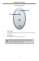
IR REMOTE CONTROL Layout and Descriptions 1 2 1 LED Indicator This LED will be activated momentarily each time one of the two buttons are pressed. 2 Input Selection Press these buttons to select the input source. NOTE: An Activity Indicator that flashes quickly while holding down any one of the 16 buttons indicates a low battery. Replace the IR Remote Control battery as soon as possible.
IR REMOTE CONTROL Installing the Battery The Remote Control unit ships with two batteries. One battery is required for operation and the other battery is a spare. 1. Remove the battery cover on the back of the IR Remote Control unit. 2. Insert the included battery into the open battery slot. The positive (+) side of the battery should be facing up. 3. Replace the batteryy cover.
CONNECTING THE 2X1 DVIKVM DL SWITCH How to Connect the 2X1 DVIKVM DL Switch 1. Connect the included dual-link DVI cables between the DVI outputs of each computer to the DVI input connectors on the 2X1 DVIKVM DL Switch. 2. Connect the included USB cables from each computer to the USB In ports on the 2X1 DVIKVM DL Switch. 3. Connect the included 3.5mm mini-stereo cables from each computer / audio source to the 3.5mm mini-stereo jacks on the 2X1 DVIKVM DL Switch. 4.
OPERATING THE 2X1 DVIKVM DL SWITCH Switching sources Use the Select button on the front panel or the included IR Remote Control unit to switch between sources. Switching using the front panel • Press the Select button on the front panel to toggle between input 1 (DVI In 1) and input 2 (DVI In 2).
OPERATING THE 2X1 DVIKVM DL SWITCH Switching using the RMT2 (not included) 1. Connect the RMT2 Remote (Gefen part no. EXT-RMT-2) to the Remote jack on the 2X1 DVIKVM DL Switch, using a 3.5mm mini-stereo cable. 2. Press the button on the front of the RMT2 Remote to switch between DVI In 1 and DVI In 2.
OPERATING THE 2X1 DVIKVM DL SWITCH Switching using Contact Closure 1. Locate the DIP switch bank on the bottom of the 2x1 DVIKVM Switch. 2. Set DIP switch 3 to the ON position to enable discrete contact closure switching. Set DIP 3 to the ON position NOTE: When DIP switch 3 is set to the ON position, then the 2x1 DVIKVM DL Switch will no longer receive IR commands from the IR Remote Control unit. Set DIP switch 3 to the OFF position to re-enable IR control.
OPERATING THE 2X1 DVIKVM DL SWITCH When discrete contact closure switching is enabled, the following actions are valid: • If the remote wire is note shorted, then DVI In 1 will always be selected. • If the ring is shorted to the sleeve, then DVI In 2 will always be selected. The diagram below outlines a typical 3.5mm mini-stereo TRS (Tip-Ring-Sleeve) connector.
OPERATING THE 2X1 DVIKVM DL SWITCH Using the IR Extender (not included) 1. On the bottom of the 2x1 DVIKVM DL Switch, locate the DIP switch bank and set DIP switch 4 to the ON position. Set DIP 4 to the ON position 2. Connect the IR Extender to the Remote jack on the 2x1 DVIKVM DL Switch. 3. Point the IR Remote Control unit at the IR Extender to control the 2x1 DVIKVM DL Switch.
SPECIFICATIONS Maximum Pixel Clock................................................................................ 165 MHz Video Input Connectors................................. (2) DVI-I 29 pin, female (digital only) Video Output Connector.................................(1) DVI-I 29 pin, female (digital only) Audio Input Connectors............................................... (2) 3.5 mm mini-stereo jack Audio Output Connector...............................................(1) 3.
WARRANTY Gefen warrants the equipment it manufactures to be free from defects in material and workmanship. If equipment fails because of such defects and Gefen is notified within two (2) years from the date of shipment, Gefen will, at its option, repair or replace the equipment, provided that the equipment has not been subjected to mechanical, electrical, or other abuse or modifications.
Rev A4 Pb This product uses UL or CE listed power supplies.