
User manual

17
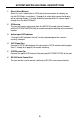
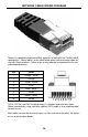
The 8X8 DVI Matrix has 4 banks of DIP Switches located on the underside of the
main unit. This section will outline the function of each DIP Switch bank.
DIP SWITCH BANKS
DIP Switch Description
1
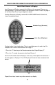
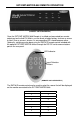
RMT-848IR remote control channel confi guration. This
setting must match DIP Switch 1 on the RMT-848IR remote
control.
2
RMT-848IR remote control channel confi guration. This
setting must match DIP Switch 2 on the RMT-848IR remote
control.
3 NOT USED
4 NOT USED
5 NOT USED
6 NOT USED
7 NOT USED
8
General +5V enable on all outputs for use with fi ber optic
products that require 5V for operation.
[OFF] Feature disabled [ON] +5V DC enabled.
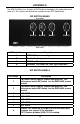
DIP Switch Bank Description
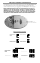
A RMT-848IR channel confi guration
B Monitor Pre-Emphasis
C EDID Pass Through
D Individual +5V Enable for Fiber Optic extenders
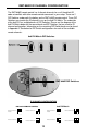
DIP SWITCH BANK A
APPENDIX A
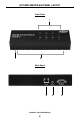
Rear Panel
Front Panel
Bank A Bank B Bank C Bank D