® 8x8 DVI Matrix EXT-DVI-848 User Manual www.gefen.
ASKING FOR ASSISTANCE Technical Support: Telephone Fax (818) 772-9100 (800) 545-6900 (818) 772-9120 Technical Support Hours: 8:00 AM to 5:00 PM Monday thru Friday Pacific Time Write To: Gefen, LLC c/o Customer Service 20600 Nordhoff St Chatsworth, CA 91311 www.gefen.com support@gefen.com Notice Gefen, LLC reserves the right to make changes in the hardware, packaging and any accompanying documentation without prior written notice.
CONTENTS 1 Introduction 2 Operation Notes 3 Features 4 8x8 DVI Matrix Front Panel Layout 5 8x8 DVI Matrix Front Panel Descriptions 6 8x8 DVI Matrix Back Panel Layout 7 8x8 DVI Matrix Back Panel Descriptions 8 EXT-RMT-Matrix-848 Panel Layout 9 EXT-RMT-Matrix-848 Panel Descriptions 10 Connecting And Operating The 8x8 DVI Matrix 11 8x8 DVI Matrix Remote Description & Operation 12 RMT-848IR IR Channel Configuration 13 EXT-RMT-Matrix-848 Remote Operation 14 RMT-8-IR IR Channel Configuration 15
INTRODUCTION Congratulations on your purchase of the 8x8 DVI Matrix. Your complete satisfaction is very important to us. Gefen Gefen delivers innovative, progressive computer and electronics add-on solutions that harness integration, extension, distribution and conversion technologies.
OPERATION NOTES READ THESE NOTES BEFORE INSTALLING OR OPERATING THE 8X8 DVI MATRIX • The 8x8 DVI Matrix is HDCP compliant when used in EDID pass-through mode (when a single DVI input is mapped to a single DVI output). Additional Matrix outputs which attempt to route video signals to a source device that has already made an HDCP connection with an HDCP-compliant display will not be able to display an image. • By default, EDID routing is based on the first connected source and display.
FEATURES Features • Increases your productivity by providing you with access to eight computers from eight workstations • Maintains beautiful, sharp HDTV resolutions up to 1080p, 2K, and 1920x1200 • Discrete IR remote control included • Long-distance remote control at distances of up to 330 feet using optional wired CAT5 cabled remotes • Serial RS232 port for remote control via computer or a control automation device such as Crestron • Supports DDWG standards for DVI monitors.
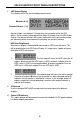
1 2 3 8X8 DVI MATRIX FRONT PANEL LAYOUT 4
X8 DVI MATRIX FRONT PANEL DESCRIPTIONS 1 LED Status Display This display will list the current display/source routes. Monitor (A~H) Selected Source (1~8) Monitor Output’s are labeled 1 through 8 on the rear panel of the 8x8 DVI Matrix. These numbers correspond to the letters A through H on the LED Status Display. The top row of letters will remain static while each input number below will represent which source each of the displays are currently viewing.
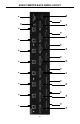
18 10 1 19 2 11 20 3 12 21 4 13 22 5 14 6 23 15 7 24 16 8 25 27 17 26 9 8X8 DVI MATRIX BACK PANEL LAYOUT 6
8X8 DVI MATRIX BACK PANEL DESCRIPTIONS 1-8 Optional Remote Switching Ports Ports 1 through 8 are used for remote switching using the optional component EXT-RMT-MATRIX-848. 9 RS-232 Serial Control Interface This port is used for serial communication for multiple functions. Access to certain features are only through the RS-232 interface. 10-17 DVI Input Ports Connect up to 8 DVI sources to DVI Input Ports 1 through 8. 18-25 DVI Output Ports Connect up to 8 DVI displays to DVI Output Ports 1 through 8.
EXT-RMT-MATRIX-848 PANEL LAYOUT Front Panel 1 2 3 Back Panel 4 (PRODUCT SOLD SEPARATELY) 8 5 6
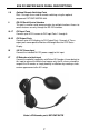
EXT-RMT-MATRIX-848 PANEL DESCRIPTIONS 1 Direct Select Buttons When this unit is attached to a CAT-5 port that corresponds to a display on the 8x8 DVI Matrix, use buttons 1 through 8 to select what source that display will be viewing. Buttons 1 through 8 directly correspond to DVI source inputs 1 through 8 on the 8x8 DVI Matrix. 2 IR Receiver This port will receive commands from the RMT-8-IR remote control (included with the EXT-RMT-MATRIX-848) for remote controlled switching at the extended location.
CONNECTING AND OPERATING THE 8X8 DVI MATRIX How to Connect the 8x8 DVI Matrix 1. Connect up to 8 DVI sources to the DVI Input ports on the 8x8 DVI Matrix using the supplied DVI cables. 2. Connect up to 8 DVI displays to the DVI Output ports on the 8x8 DVI Matrix using user supplied DVI cables. 3. Optionally connect up to 8 remote switching units (Part# EXT-RMT-MATRIX848) to the RJ-45 Input ports on the rear panel on the 8x8 DVI Matrix using user supplied CAT-5, CAT-5e or CAT-6.
8X8 DVI MATRIX REMOTE DESCRIPTION & OPERATION How to Route Sources to Displays Input Sources and Displays connect to the Matrix on the rear panel. Sources use input connectors 1 thru 8 while Displays use connectors A thru H. Please see page 6 for the Matrix Back Panel Layout diagram for details. Routing a Source to a Display is done with the RMT-848IR Remote Control unit, shown immediately below. Number Keys (Sources) Letter Keys (Displays) Routing is done in two simple steps.
RMT-848IR IR CHANNEL CONFIGURATION The RMT-848IR remote control has 4 discrete channels for use if the default IR code set conflicts with other remote control commands in your setup. There are 2 DIP Switches underneath the battery on the RMT-848IR remote control. These DIP Switches must match the IR channel in use on the 8x8 DVI Matrix. The underside of the 8x8 DVI has multiple banks of DIP Switches.
EXT-RMT-MATRIX-848 REMOTE OPERATION (PRODUCT SOLD SEPARATELY) Once the EXT-RMT-MATRIX-848 Remote is installed and connected to a remote output port on the 8x8 DVI Matrix, use the direct selection buttons to chose a source to view. Once a source is chosen, its corresponding LED should become active. Optionally, switching can be done using the RMT-8-IR remote control included with the optional EXT-RMT-MATRIX-848 or through the RS-232 serial communications port on the rear panel.
RMT-8-IR IR CHANNEL CONFIGURATION The RMT-8-IR remote control (included with purchase of the EXT-RMT-MATRIX-848) has 4 discrete IR channels for use if the default IR code set conflicts with other remote control commands in your setup. There are 2 DIP Switches underneath the battery compartment cover on the RMT-8-IR remote control that must match DIP Switches on the EXT-RMT-MATRIX-848. There are 4 DIP Switches located on the underside of the EXT-RMT-MATRIX-848.
RS-232 SERIAL CONTROL INTERFACE 54321 12345 9876 6789 Only Pins 2 (RX), 3 (TX), and 5 (Ground) are used on the RS-232 serial interface RS232 Settings Bits per second ................................................................................................. 19200 Data bits .................................................................................................................... 8 Parity ....................................................................................................
NETWORK CABLE WIRING DIAGRAM Gefen has specifically engineered their products to work with the TIA/EIA-568-B specification. Please adhere to the table below when field terminating cable for use with Gefen products. Failure to do so may produce unexpected results and reduced performance. Pin Color 1 Orange / White 2 Orange 3 Green / White 4 Blue 5 Blue / White 6 Green 7 Brown / White 8 Brown 12345678 CAT-5, CAT-5e, and CAT-6 cabling comes in stranded and solid core types.
APPENDIX A The 8X8 DVI Matrix has 4 banks of DIP Switches located on the underside of the main unit. This section will outline the function of each DIP Switch bank. DIP SWITCH BANKS Front Panel Bank A Bank B Bank C Bank D Rear Panel DIP Switch Bank Description A RMT-848IR channel configuration B Monitor Pre-Emphasis C EDID Pass Through D Individual +5V Enable for Fiber Optic extenders DIP SWITCH BANK A DIP Switch Description 1 RMT-848IR remote control channel configuration.
APPENDIX A DIP SWITCH BANK B DIP Switch Monitor Description 1 A [OFF] 0 db pre-emphasis, [ON] 6 db pre-emphasis 2 B [OFF] 0 db pre-emphasis, [ON] 6 db pre-emphasis 3 C [OFF] 0 db pre-emphasis, [ON] 6 db pre-emphasis 4 D [OFF] 0 db pre-emphasis, [ON] 6 db pre-emphasis 5 E [OFF] 0 db pre-emphasis, [ON] 6 db pre-emphasis 6 F [OFF] 0 db pre-emphasis, [ON] 6 db pre-emphasis 7 G [OFF] 0 db pre-emphasis, [ON] 6 db pre-emphasis 8 H [OFF] 0 db pre-emphasis, [ON] 6 db pre-emphasis DIP SWITCH
EDID MANAGEMENT QUICK START GUIDE To use EDID Management functions, the EDID mode must be changed from Pass-Through to LOCAL. Please follow the steps below to set this mode. NOTE: LOCAL EDID mode does not support HDCP. 1. Locate Bank C on the underside of the 8x8 DVI Matrix. 2. Each input has a DIP switch associated with it. Select the inputs that will be changed to LOCAL mode and flip their DIP switch to the ON position. By default, all DIP switches are in the Pass-Through mode (OFF).
APPENDIX B The 8X8 DVI Matrix uses RS-232 serial communication for access to a number of features. Please us this section for EDID storing, calling, and routing functions. REMOTE FUNCTION The remote functions are used to modify the setting of the product, such as: Input to output routing, EDID memory management etc. These functions are available only via serial communications on the RS-232 port.
APPENDIX B Example: #FunctionName_param1_param2_param3_param4…\r Set Preset Routing State This function enables the user to determine up to 10 routing states to save in memory.
APPENDIX B Unmask Masked Outputs This function unmasks outputs that were masked by “#MASK” #UNMASK_param1[_param2][_param3][_param4][_param5] [_param6][_param7][_param8]\r Parameter Name Value 1 (2-8 optionally) MONITOR [A : H] RMT-848IR Address This function set the remote channel that must match the GEFEN RMT-848IR remote control. #RMT_param1\r Parameter Value 1 [0:3] DS EDID Store In Locals Edid This function reads EDID file from DS and store it in any input Locals EDID.
APPENDIX B EDID From Bank Store In Locals EDID This function reads an EDID file from the EDID bank and stores it in any Input’s local EDID. #EDIDBATOLO_param1_param2[_param3][_param4][_param5][_param6] [_param7][_param8][_param9]\r Parameter Name Value 1 EDID bank offset [1:7] 2 (3-9 optionally) INPUT [1:8] Route Input DDC To Local EDID This function routes the Input DDC to the Local EDID.
APPENDIX B #PRBAEDID_param1_param2\r Parameter Name Value 1 EDID bank offset [1:7] Send BIN file 0 Send TXT file 1 2 Print EDID Setting This function sends the EDID setting table to the serial port. #PRSEEDID\r Load EDID To Locals EDID These functions will load an EDID file through the serial port and store it in any Input’s Local EDID.
APPENDIX B Set Output Pre Emphasis This function will set output Pre Emphasis in db. #PE_param1_param2\r Parameter Name Value 1 MONITOR [A:H] 2 Pre Emp. level [db] [0,2,4,6] Set Default Setting This function will set the product back to its default setting. 1. 2. Routing state will be INPUT1-MONA, INPUT2-MONB, …, All the features with default to how the hardware switches are set. The DVI and HDMI 8x8 has the following shortcut routing commands.
SPECIFICATIONS Video Amplifier Bandwidth ................................................... 165 MHz per channel Single Link Range .............................................. 1080p (HDTV) / 1920x1200 (PC) Input Video Signal .............................................................................. 1.2 Volts p-p Input DDC Signal ......................................................................... 5 Volts p-p (TTL) Remote Control Ports ..................................
WARRANTY Gefen warrants the equipment it manufactures to be free from defects in material and workmanship. If equipment fails because of such defects and Gefen is notified within two (2) years from the date of shipment, Gefen will, at its option, repair or replace the equipment, provided that the equipment has not been subjected to mechanical, electrical, or other abuse or modifications.
*ma-DVI-848* Rev A7 20600 Nordhoff St., Chatsworth CA 91311 1-800-545-6900 818-772-9100 www.gefen.com fax: 818-772-9120 support@gefen.