8x8 DVI Matrix EXT-DVI-848 User Manual www.gefen.
ASKING FOR ASSISTANCE Technical Support: Telephone Fax (818) 772-9100 (800) 545-6900 (818) 772-9120 Technical Support Hours: 8:00 AM to 5:00 PM Monday thru Friday. Write To: Gefen Inc. c/o Customer Service 20600 Nordhoff St Chatsworth, CA 91311 www.gefen.com support@gefen.com Notice Gefen Inc. reserves the right to make changes in the hardware, packaging and any accompanying documentation without prior written notice. 8x8 DVI Matrix is a trademark of Gefen Inc. © 2008 Gefen Inc.
CONTENTS 1 Introduction 2 Operation Notes 3 Features 4 8x8 DVI Matrix Front Panel Layout 5 8x8 DVI Matrix Front Panel Descriptions 6 8x8 DVI Matrix Back Panel Layout 7 8x8 DVI Matrix Back Panel Descriptions 8 EXT-RMT-Matrix-848 Panel Layout 9 EXT-RMT-Matrix-848 Panel Descriptions 10 Connecting And Operating The 8x8 DVI Matrix 11 8x8 DVI Matrix Remote Description & Operation 12 RMT-16-IR IR Channel Configuration 13 EXT-RMT-Matrix-848 Remote Operation 14 RMT-8-IR IR Channel Configuration 15
INTRODUCTION Congratulations on your purchase of the 8x8 DVI Matrix. Your complete satisfaction is very important to us. Gefen Gefen delivers innovative, progressive computer and electronics add-on solutions that harness integration, extension, distribution and conversion technologies.
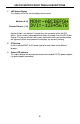
OPERATION NOTES READ THESE NOTES BEFORE INSTALLING OR OPERATING THE 8X8 DVI MATRIX • 8x8 DVI Matrix is not HDCP compliant • By default, EDID routing is based on the first connected display to a source. For example, if monitor A is the first display to connect to source 1 its EDID will be used. All other displays that connect to source 1 thereafter will have its EDID ignored.
FEATURES Features • Increases your productivity by providing you with access to eight computers from eight workstations • Maintains beautiful, sharp HDTV resolutions up to 1080p, 2K, and 1920x1200 • Discrete IR remote control included • Long-distance remote control at distances of up to 330 feet using optional wired CAT5 cabled remotes • Serial RS232 port for remote control via computer or a control automation device such as Crestron • Supports DDWG standards for DVI monitors • Not HDCP complia
1 2 3 8X8 DVI MATRIX FRONT PANEL LAYOUT 4
X8 DVI MATRIX FRONT PANEL DESCRIPTIONS 1 LED Status Display This display will list the current display/source routes. Monitor (A~H) Selected Source (1~8) Monitor Output’s are labeled 1 through 8 on the rear panel of the 8x8 DVI Matrix. These numbers correspond to the letters A through H on the LED Status Display. The top row of letters will remain static while each input number below will represent which source each of the displays are currently viewing.
18 10 1 19 2 11 20 3 12 21 4 13 22 5 14 6 23 15 7 24 16 8 25 17 26 9 8X8 DVI MATRIX BACK PANEL LAYOUT 6
8X8 DVI MATRIX BACK PANEL DESCRIPTIONS 1-8 Optional Remote Switching Ports Ports 1 through 8 are used for remote switching using the optional component EXT-RMT-MATRIX-848. 9 RS-232 Serial Control Interface This port is used for serial communication for multiple functions. Access to certain features are only through the RS-232 interface. 10-17 DVI Input Ports Connect up to 8 DVI sources to DVI Input Ports 1 through 8. 18-25 DVI Output Ports Connect up to 8 DVI displays to DVI Output Ports 1 through 8.
EXT-RMT-MATRIX-848 PANEL LAYOUT Front Panel 1 2 3 Back Panel 4 (PRODUCT SOLD SEPARATELY) 8 5 6
EXT-RMT-MATRIX-848 PANEL DESCRIPTIONS 1 Direct Select Buttons When this unit is attached to a CAT-5 port that corresponds to a display on the 8x8 DVI Matrix, use buttons 1 through 8 to select what source that display will be viewing. Buttons 1 through 8 directly correspond to DVI source inputs 1 through 8 on the 8x8 DVI Matrix. 2 IR Receiver This port will receive commands from an RMT-8-IR remote control for remote controlled switching at the extended location.
CONNECTING AND OPERATING THE 8X8 DVI MATRIX How to Connect the 8x8 DVI Matrix 1. Connect up to 8 DVI sources to the DVI Input ports on the 8x8 DVI Matrix using the supplied DVI cables. 2. Connect up to 8 DVI displays to the DVI Output ports on the 8x8 DVI Matrix using user supplied DVI cables. 3. Optionally connect up to 8 remote switching units (Part# EXT-RMT-MATRIX848) to the RJ-45 Input ports on the rear panel on the 8x8 DVI Matrix using user supplied CAT-5, CAT-5e or CAT-6.
8X8 DVI MATRIX REMOTE DESCRIPTION & OPERATION Buttons 1 through 8 on the RMT-16 IR remote control correspond to display outputs ns 9 through 16 correspond to source inputs 1 through t A through H. Buttons 8. Please vide sources to use the steps and chart below for instructions on how to route video displays.
RMT-16-IR IR CHANNEL CONFIGURATION The RMT-16-IR remote control has 4 discrete channels for use if the default IR code set conflicts with other remote control commands in your setup. There are 2 DIP Switches underneath the battery on the RMT-16-IR remote control. These DIP Switches must match the IR channel in use on the 8x8 DVI Matrix. The underside of the 8x8 DVI has multiple banks of DIP Switches.
EXT-RMT-MATRIX-848 REMOTE OPERATION (PRODUCT SOLD SEPARATELY) Once the EXT-RMT-MATRIX-848 Remote is installed and connected to a remote output port on the 8x8 DVI Matrix, use the direct selection buttons to chose a source to view. Once a source is chosen, its corresponding LED should become active. Optionally, switching can be done using an RMT-8-IR remote control (sold separately) or through the RS-232 serial communications port on the rear panel.
RMT-8-IR IR CHANNEL CONFIGURATION The RMT-8-IR remote control (sold separately) has 4 discrete IR channels for use if the default IR code set conflicts with other remote control commands in your setup. There are 2 DIP Switches underneath the battery on the RMT-8-IR remote control that must match DIP Switches on the EXT-RMT-MATRIX-848. There are 4 DIP Switches located on the underside of the EXT-RMT-MATRIX-848.
RS-232 SERIAL CONTROL INTERFACE 12345 12345 6789 6789 Only Pins 2 (RX), 3 (TX), and 5 (Ground) are used on the RS-232 serial interface RS232 Settings Bits per second ................................................................................................. 19200 Data bits .................................................................................................................... 8 Parity ....................................................................................................
NETWORK CABLE WIRING DIAGRAM Gefen has specifically engineered their products to work with the TIA/EIA-568-B specification. Please adhere to the table below when field terminating cable for use with Gefen products. Failure to do so may produce unexpected results and reduced performance. Pin Color 1 Orange / White 2 Orange 3 Green / White 4 Blue 5 Blue / White 6 Green 7 Brown / White 8 Brown 12345678 CAT-5, CAT-5e, and CAT-6 cabling comes in stranded and solid core types.
APPENDIX A The 8X8 DVI Matrix has 4 banks of DIP Switches located on the underside of the main unit. This section will outline the function of each DIP Switch bank. DIP SWITCH BANKS Front Panel Bank A Bank B Bank C Bank D Rear Panel DIP Switch Bank Description A • RMT-16-IR channel configuration B • Monitor pre-emphasis C • For future implementation D • For future implementation DIP SWITCH BANK A DIP Switch Description 1 RMT-16-IR remote control channel configuration.
APPENDIX A DIP SWITCH BANK B DIP Switch Monitor Description 1 A [OFF] 0 db pre-emphasis, [ON] 6 db pre-emphasis 2 B [OFF] 0 db pre-emphasis, [ON] 6 db pre-emphasis 3 C [OFF] 0 db pre-emphasis, [ON] 6 db pre-emphasis 4 D [OFF] 0 db pre-emphasis, [ON] 6 db pre-emphasis 5 E [OFF] 0 db pre-emphasis, [ON] 6 db pre-emphasis 6 F [OFF] 0 db pre-emphasis, [ON] 6 db pre-emphasis 7 G [OFF] 0 db pre-emphasis, [ON] 6 db pre-emphasis 8 H [OFF] 0 db pre-emphasis, [ON] 6 db pre-emphasis DIP SWITCH
APPENDIX B The 8X8 DVI Matrix uses RS-232 serial communication for access to a number of features. Please us this section for EDID storing, calling, and routing functions. REMOTE FUNCTION The remote functions are used to modify the setting of the product, such as: Input to output routing, EDID memory management etc. These functions are available only by the serial communications port. Modify By Shortcut Switching Command First character indicates the output monitor.
APPENDIX B DS EDID Store In Locals Edid This function reads EDID file from DS and store it in any input Locals EDID. #EDIDDSTOLO_param1_param2[_param3][_param4][_param5] [_param6] [_param7][_param8][_param9]\r Parameter Name Value 1 MONITOR [A:H] 2 (3-9 optionally) INPUT [1:8] DS EDID Store In EDID Bank This function reads EDID file from DS and store it in EDID bank.
APPENDIX B Route Input DDC To Local EDID This function routes the Input DDC to the Local EDID. #DDCTOLO_param1\r Parameter Name Value 1 INPUT [1:8] Print DS EDID This function reads the DS EDID file and sends it to the serial port. #PRDSEDID_param1_param2\r Parameter Name Value 1 MONITOR [A:H] 2 Send BIN file 0 Send TXT file 1 Print Local EDID This function reads the Input Local EDID file and sends it to the serial port.
APPENDIX B Print EDID Setting This function sends the EDID setting table to the serial port. #PRSEEDID\r Load EDID To Locals EDID These functions will load an EDID file through the serial port and store it in any Input’s Local EDID. #LOEDIDTOLO_param1_param2_param3[_param4][_param5][_param6] [_param7][_param8][_param9][_param10]\r Parameter 1 2 3 (4-10 optionally) Name Value Semi echo mode 0 Full echo mode 1 EDID.bin file (256 bytes) 1 EDID.
APPENDIX B Set Default Setting This function will set the product back to its default setting. 1. 2. Routing state will be INPUT1-MONA, INPUT2-MONB, …, All the features with default to how the hardware switches are set. #DEF\r Set Preset Routing State This function enables the user to determine up to 10 routing states to save in memory.
SPECIFICATIONS Video Amplifier Bandwidth ................................................... 165 MHz per channel Single Link Range .............................................. 1080p (HDTV) / 1920x1200 (PC) Input Video Signal .............................................................................. 1.2 Volts p-p Input DDC Signal ......................................................................... 5 Volts p-p (TTL) Remote Control Ports ..................................