® 4x1 DPKVM Switcher EXT-DPKVM-441 User Manual www.gefen.
ASKING FOR ASSISTANCE Technical Support: Telephone Fax (818) 772-9100 (800) 545-6900 (818) 772-9120 Technical Support Hours: 8:00 AM to 5:00 PM Monday thru Friday. Write To: Gefen LLC c/o Customer Service 20600 Nordhoff St Chatsworth, CA 91311 www.gefen.com support@gefen.com Notice Gefen LLC reserves the right to make changes in the hardware, packaging and any accompanying documentation without prior written notice. 4x1 DPKVM Switcher is a trademark of Gefen LLC © 2011 Gefen, LLC. All rights reserved.
CONTENTS 1 Introduction 2 Operation Notes 3 Features 4 Front Panel Layout 5 Front Panel Descriptions 6 Back Panel Layout 7 Back Panel Descriptions 8 IR Remote Control Unit 8 Layout and Description 9 Installing the Battery 10 Setting the IR Channel 11 Connecting the 4x1 DPKVM Switcher 11 Wiring Diagram 12 Operating the 4x1 DPKVM Switcher 12 Front Panel Buttons and LED Indicators 12 Switching sources using the front panel buttons 12 Switching sources using the IR Remote Control Un
INTRODUCTION Congratulations on your purchase of the 4x1 DPKVM Switcher. Your complete satisfaction is very important to us. Gefen Gefen delivers innovative, progressive computer and electronics add-on solutions that harness integration, extension, distribution and conversion technologies.
OPERATION NOTES READ THESE NOTES BEFORE INSTALLING OR OPERATING THE 4X1 DPKVM SWITCHER • The 4x1 DPKVM Switcher supports Pass-through EDID. The Switcher will use the EDID from the monitor connected to the output. • Dual Link resolutions up to 2560 x 1600 are supported. • HDCP content is not supported. • This Switcher does not support DHCP. • The default IR channel for both the Switcher and the IR Remote Control Unit is channel 0. See page 10 for more information.
FEATURES Features • Front panel switching using discrete select buttons • Supports resolutions up to 2560 x 1600 • Supports RGB and YCbCr color spaces • RS-232 control • IP control • IR remote control • Supports USB 2.0 with backward-compatibility for USB 1.1 • Jack for external IR Receiver (EXT-RMT-EXTIR) • Save space on your desktop • Rack-mountable Package Includes (1) 4x1 DPKVM Switcher (4) 6 ft. DisplayPort cables (4) 6 ft. USB 2.0 cables (A - B) (4) 6 ft. 3.
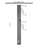
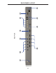
1 Front Panel 2 3 4 FRONT PANEL LAYOUT 4
FRONT PANEL DESCRIPTIONS 1 Input Indicators (1 - 4) Each of these LED indicators glows bright blue according to the input selection (see Input Buttons, below) 2 IR Receives IR signals from the included IR Remote Control Unit. 3 Input Buttons (1 - 4) Pressing each of these buttons selects the desired input source (1-4). 4 Power This LED indicator will glow bright red when the unit is powered.
1 10 2 9 Back Panel 8 3 4 7 6 5 BACK PANEL LAYOUT 6
BACK PANEL DESCRIPTIONS 1 5V DC Connect the included 5V DC locking power supply to this receptacle. 2 DP In 1 - In 4 Each of these ports will accept a standard DisplayPort source device. 3 Ext IR Connect an IR extender cable to this port. 4 USB Out (1 - 2) Connect USB devices (e.g. mouse devices, keyboards, etc.) to these ports. 5 Ethernet Use an Ethernet cable to connect the Switcher to a network in order to communicate via Telnet.
IR REMOTE CONTROL UNIT Layout and Description 1 2 1 Activity Indicator This LED will be activated momentarily each time a button is pressed. 2 Source Selection Buttons (1 - 4) These buttons are used to select which source is routed to a monitor. NOTE: An Activity Indictor that flashes quickly while holding down any one of the four buttons indicates a low battery. Replace the IR Remote Control battery as soon as possible.
IR REMOTE CONTROL UNIT Installing the Battery 1. Remove the battery cover on the back of the IR Remote Control Unit. 2. Insert the included battery into the open battery slot. The positive (+) side of the battery should be facing up. 3. Replace the battery cover. The Remote Control unit ships with two batteries. One battery is required for operation and the other battery is a spare. Battery Slot WARNING: Risk of explosion if battery is replaced by an incorrect type.
IR REMOTE CONTROL UNIT Setting the IR Channel In the event that IR commands from other remote controls interfere with the supplied IR Remote Control unit, changing the IR Remote Control’s IR channel will fix the problem. The IR Remote Control unit has a bank of DIP switches used for setting the IR channel. The DIP switch bank is located underneath the battery cover. Left: Picture of the opened rear battery compartment of the IR remote showing the exposed DIP Switch bank between the battery chambers.
CONNECTING THE 4X1 DPKVM SWITCHER How to Connect the 4x1 DPKVM Switcher 1 Connect up to four (4) DisplayPort source devices to the DisplayPort inputs on the back panel of the Switcher using DisplayPort cables. 2 Connect a DisplayPort-supported display to the DisplayPort output on the back panel of the Switcher. a OPTIONAL: To use the RS-232 communication feature, connect an RS-232 cable between the Switcher and RS-232 host controller.
OPERATING THE 4X1 DPKVM SWITCHER Front Panel Buttons and LED Indicators The front panel of the 4x1 DPKVM Switcher has a set of four (4) LED indicators, displaying which input (source) is being displayed. Each of these LED indicators corresponds to one of the push-buttons on the front panel. Switching sources using the front panel buttons Example: Switch to input 3 using the front panel buttons: 1 Press button 3 on the front panel of the 4x1 DPKVM Switcher.
OPERATING THE 4X1 DPKVM SWITCHER Switching sources using RS-232 Configure the Switch for use with RS-232 (see page 14 for details). Example: Switch to input 4 using RS-232 1 Use the command r 4 to route the Switcher to Input 4. See page 15 for important information on RS-232 commands. RS-232 commands are case-sensitive. 2 The LED indicator for Input 4 will glow bright blue on the front panel. 1 2 r 4 Route to Input 4 Switching sources using Telnet Configure the Switch for use with Telnet.
RS-232 CONTROL Only pins 2 (Receive), 3 (Transmit), and 5 (Ground) are used for communication. A null-modem adapter should not be used with this product. 54321 12345 9876 6789 Only Pins 2 (RX), 3 (TX), and 5 (Ground) are used on the RS-232 serial interface Serial Port Settings Bits per second ............................................................................................ 19200 Data bits .......................................................................................................
RS-232 COMMANDS Command Syntax All RS-232 commands are case-sensitive and must be entered in lowercase. Each command must be preceded by the ‘#’ character. A carriage return must also be appended to every command.
RS-232 COMMANDS #GET_USER_NAME Command The #GET_USER_NAME command prompts for the Telnet username. Syntax: #get_user_name Parameters: None #IPCONFIG Command The #IPCONFIG command displays all TCP/IP settings. Syntax: #ipconfig Parameters: None #RSTIP Command The #RSTIP command resets the IP configuration to the default settings.
RS-232 COMMANDS #SET_HTTP_PORT Command The #SET_HTTP_PORT command sets the Web server listening port. Syntax: #set_http_port param1 Parameters: param1 Port [0 - 255] #SET_PASS Command The #SET_PASS command sets Telnet password. Syntax: #set_pass param1 Parameters: param1 String Notes: The maximum length of the password string is 20 characters. #SET_TELNET_PORT Command The #SET_TELNET_PORT command sets the Telnet server listening port.
RS-232 COMMANDS #SET_USER_NAME Command The #SET_USER_NAME command sets the Telnet user name. Syntax: #set_user_name param1 Parameters: param1 String Notes: The maximum length of the username string is 20 characters. #SGATEWAY Command Specifies the new IP gateway. Dot-decimal notation must be used when specifying the IP address. A reboot is required after the new IP gateway address has been assigned. Syntax: #sgateway param1.param2.param3.
RS-232 COMMANDS #SIPADD Command The #SIPADD command specifies a new IP address. Dot-decimal notation must be used when specifying the IP address. A reboot is required after the new IP address is set. Syntax: #sipadd param1.param2.param3.param4 Parameters: param1 IP address [0 - 255] param2 IP address [0 - 255] param3 IP address [0 - 255] param4 IP address [0 - 255] Example: #sipadd 192.168.2.240 #SNETMASK Command The #SNETMASK command specifies a new net mask.
RS-232 COMMANDS #USE_TELNET_PASS Command The #USE_TELNET_PASS command enables / disabled the use of a Telnet password during the login process.
RS-232 COMMANDS #FADEFAULT Function The #FADEFAULT function will reset the Switcher to the default routing settings. Syntax: #fadefault Parameters: None #IRRMTADD Command The #IRRMTADD sets the IR channel. The IR channel for the Switcher and the IR Remote Control Unit must be the same.
RS-232 COMMANDS #LOCKPOWER Command The #LOCKPOWER enables/disables the power lock state. Enabling this feature will store the 5V status for each input prior to shutting the unit down. This preserves the 5V state when the unit is restarted. Syntax: #lockpower param1 Parameters: param1 State [0 - 1] Value Meaning 0 Disable Power Lock 1 Enable Power Lock #STBYMODE Command The #STBYMODE command toggles the Standby Mode state.
RS-232 COMMANDS Routing Commands The following command does not require the ‘#’ character. A carriage return must be added to the end of the command. Command Description R Routing command R Command The R command switches to the specified input.
TELNET CONTROL The Gefen 4x1 DPKVM Switcher supports Telnet for controlling the Switcher over a network. To access this feature, an IP address, subnet, gateway, and port numbers need to be set correctly. Consult the network administrator to obtain the proper IP address and settings for this product to properly communicate with the Switcher over a network. The Telnet control must be configured using RS-232 commands.
TELNET CONTROL 5. Use the #sipadd command to set the IP address for the Switcher. Check with a network administrator to obtain an available address, if necessary. DHCP is not supported by this Switcher. #sipadd 192.168.2.234 New IP set to: 192.168.2.234 After setting the IP address, power-cycle the Switcher for the changes to take effect. IMPORTANT: All IP configuration changes will require the Switcher to be power-cycled. 6 Specify the IP of the Switcher in the Telnet client.
FIRMWARE UPDATE Firmware Update Procedure Any terminal emulation program can be used to perform the upgrade process. The instructions below is outlined for Windows® HyperTerminal. 1. Connect an RS-232 cable between the Switcher and the computer running the terminal program. Verify the correct serial port settings (see page 14). 2. Type the #activebolo command then press the [ENTER] key. 3. Repeat Step 2.
RACK EAR INSTALLATION Installing the Rack Ears Rack mount ears are provided for installation of this unit into a 1U rack mount space. 1. 2. 3. 4. Locate the side screws on the unit. Remove the front 2 screws that are located closest to the front of the unit. Using the removed screws, screw the rack mounting bracket into the unit. Repeat the procedure on the opposite side of the unit.
SPECIFICATIONS Maximum Pixel Clock................................................................................360 MHz Video Input Connectors.......................................................(4) DisplayPort, female Video Output Connector......................................................(1) DisplayPort, female USB Input Connectors..............................................................(4) USB 2.0 Type B USB Output Connectors............................................................
WARRANTY Gefen warrants the equipment it manufactures to be free from defects in material and workmanship. If equipment fails because of such defects and Gefen is notified within two (2) years from the date of shipment, Gefen will, at its option, repair or replace the equipment, provided that the equipment has not been subjected to mechanical, electrical, or other abuse or modifications.
Rev A2 20600 Nordhoff St., Chatsworth CA 91311 1-800-545-6900 818-772-9100 www.gefen.com Pb This product uses UL listed power supplies. fax: 818-772-9120 support@gefen.