® 3GSDI to HDMI® 1.3 Converter EXT-3GSDI-2-HDMI1.3 User Manual www.gefen.
ASKING FOR ASSISTANCE Technical Support: Telephone Fax (818) 772-9100 (800) 545-6900 (818) 772-9120 Technical Support Hours: 8:00 AM to 5:00 PM Monday thru Friday, Pacific Time Write To: Gefen, LLC. c/o Customer Service 20600 Nordhoff St Chatsworth, CA 91311 www.gefen.com support@gefen.com Notice Gefen, LLC reserves the right to make changes in the hardware, packaging and any accompanying documentation without prior written notice. 3GSDI to HDMI 1.
CONTENTS 1 Introduction 2 Operation Notes 3 Features 4 Panel Layout 5 Panel Descriptions 6 Bottom Panel Layout 7 Bottom Panel Descriptions 8 Connecting And Operating The 3GSDI To HDMI 1.
INTRODUCTION Congratulations on your purchase of the 3GSDI to HDMI 1.3 Converter. Your complete satisfaction is very important to us. Gefen Gefen delivers innovative, progressive computer and electronics add-on solutions that harness integration, extension, distribution and conversion technologies.
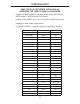
OPERATION NOTES READ THESE NOTES BEFORE INSTALLING OR OPERATING THE 3GSDI TO HDMI 1.3 CONVERTER • Supports the following SMPTE standards: 259M, 292M, SMPTE 274M, SMPTE 296M, ITU-R BT.656 and ITU-R BT.601 • Handles 3G-SDI SMPTE 425-A and 425-B / formats 1080P 50/59.94/60. • Support of 4 stereo 48 kHz audio streams. • The 3GSDI to HDMI 1.3 Converter supports the following resolutions: Video Resolution Refresh Rate (Hz) Rate 525i (NTSC) (480i) 59.94 SD 525p (480p) 59.
FEATURES Features • Field upgradable firmware using the built-in USB port. • Supports a test pattern at 720P/60 without needing a valid source signal • HMDI 1.3 compliant • Support for YCbCr, RGB, 4:2:2, 4:4:4, and 8 to 10 bits output formats. • Color space support: YCbCr, RGB. • Color sampling: 4:2:2 and 4:4:4. • Bit depth: 8, 10 bits. • Auto-detects optimal monitor format with EDID display capability information. • Support of 4 stereo 48 kHz audio streams.
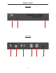
PANEL LAYOUT Front Panel 1 2 3 Back Panel 4 5 6 7 4 8 9
PANEL DESCRIPTIONS 1 Video Lock LED Indicator This indicator will become active when the SDI input (SD/HD/3G) is locked. 2 3G LED Indicator This indicator will become active when the SDI input is a 3G source. 3 Power LED Indicator This indicator will become active when power is being supplied to the unit via the included 5V DC power adapter. 4 Locking 5V DC Power Receptacle This input will accept power via the included locking 5V DC power supply.
BOTTOM PANEL LAYOUT Bottom Panel 1 2 4 5 3 6 7 6
BOTTOM PANEL DESCRIPTIONS 1 SDI Input Color Sampling LED Indicator This LED indicator will relay the status of the incoming SDI input’s color sampling. Options are either 4:4:4 (LED ON) or 4:2:2 (LED OFF). 2 SDI Input Color Space LED Indicator This LED indicator will relay the status of the incoming SDI input’s color space. Options are either RGB (LED ON) or YCbCr (LED OFF). 3 Configuration DIP Switches This DIP (Dual In-line Packages) switches will enable disable features on the 3GSDI to HDMI 1.
CONNECTING AND OPERATING THE 3GSDI TO HDMI 1.3 CONVERTER How to Connect the 3GSDI to HDMI 1.3 Converter 1. Connect the SDI source (SD/HD/3G) to the SDI input on the 3GSDI to HDMI 1.3 Converter using a user supplied SDI cable. 2. Optionally, connect an SDI capable output device to the SDI loop out connector for monitoring of the SDI input signal. 3. Optionally connect a 2 channel analog audio device to the 2 RCA style analog audio connectors for monitoring of the audio from the SDI input. 4.
DIP SWITCH FEATURES The 3GSDI to HDMI 1.3 Converter has a series of DIP switches that will allow manual configuration of the HDMI’s output video signal. There is also a DIP switch to display a test pattern through the HDMI output. Please see the next page for DIP switch features and operation.
DIP SWITCH FEATURES 3 When the EDID switch is ON (set to manual), this switch sets the output sampling of the video: 4:2:2 or 4:4:4. 4 When the EDID switch is ON (set to manual), this switch sets the output color space of the video: YCbCr or RGB. 5 When the EDID switch is ON (set to manual), and the HDMI output color is RGB, this switch specifies the video range: limited (16-235) or full range (0-255).
FIRMWARE UPDATE Things you’ll need: • Computer running Windows XP or Vista • 3GSDI Converter Firmware Loader 1.1.18 software • USB cable (to-male) • Firmware files contained in 3GSDI To HDMI Converter Firmware 1.1.5 1. Download 3GSDI Converter Firmware Loader 1.0.18 from http://www.gefen.com/kvm/support/download.jsp a. Create a new folder and decompress the downloaded file Mini_Updater_Release_1_0_18.zip into the newly created folder. b. Read and follow instructions on the Installation Guide.
FIRMWARE UPDATE 3. Download and decompress 3GSDI to HDMI Converter Firmware 1.1.5 from http://www.gefen.com/kvm/support/download.jsp to the new folder created in Step #1. 4. After installing the Firmware Loader described in Step #2, run the program via the Windows Start Menu….Start/Programs/Gefen/Mini Updater/ Mini Updater. a. Use the drop-down arrow to choose the COM port shown in Step #2. 5. Browse for the file Mini3GSDI_TO_HDMI_1_1_5.ini in the new folder created in Step#1 6.
FIRMWARE UPDATE 7. After pressing Update Device, you should see this window confirming the correct COM port, the detected device, and the firmware binary file. 8.
FIRMWARE UPDATE 9. If all steps are PASS, the firmware upload process can continue. Click YES to continue the update. If there is a FAIL, repeat steps #2-7. 10. After clicking YES, this window will appear twice showing th upload progress. 11. Once the upload process is complete, another window will pop up showing the message “Update finished”.”.
SPECIFICATIONS Max. image output resolutions: ............................2K (2048x1080), 1920x1080/60 Input Connector: ...........................................(1) BNC female SDI/HD-SDI/3G-SDI Input Connector: ............................................(1) Locking 5V DC power connector Input Connector: ..................................(1) USB connector (for firmware upgrades) Output Connector: ...........(1) BNC female SDI/HD-SDI/3G-SDI (w/buffered input) Output Connector: .............................
WARRANTY Gefen warrants the equipment it manufactures to be free from defects in material and workmanship. If equipment fails because of such defects and Gefen is notified within two (2) years from the date of shipment, Gefen will, at its option, repair or replace the equipment, provided that the equipment has not been subjected to mechanical, electrical, or other abuse or modifications.
Rev B8 20600 Nordhoff St., Chatsworth CA 91311 1-800-545-6900 818-772-9100 www.gefen.com Pb This product uses UL listed power supplies. fax: 818-772-9120 support@gefen.