
User manual


9
CONNECTING TH
E
2
X DUAL LINK DVIKVM EXTENDER OVER CAT-6
A
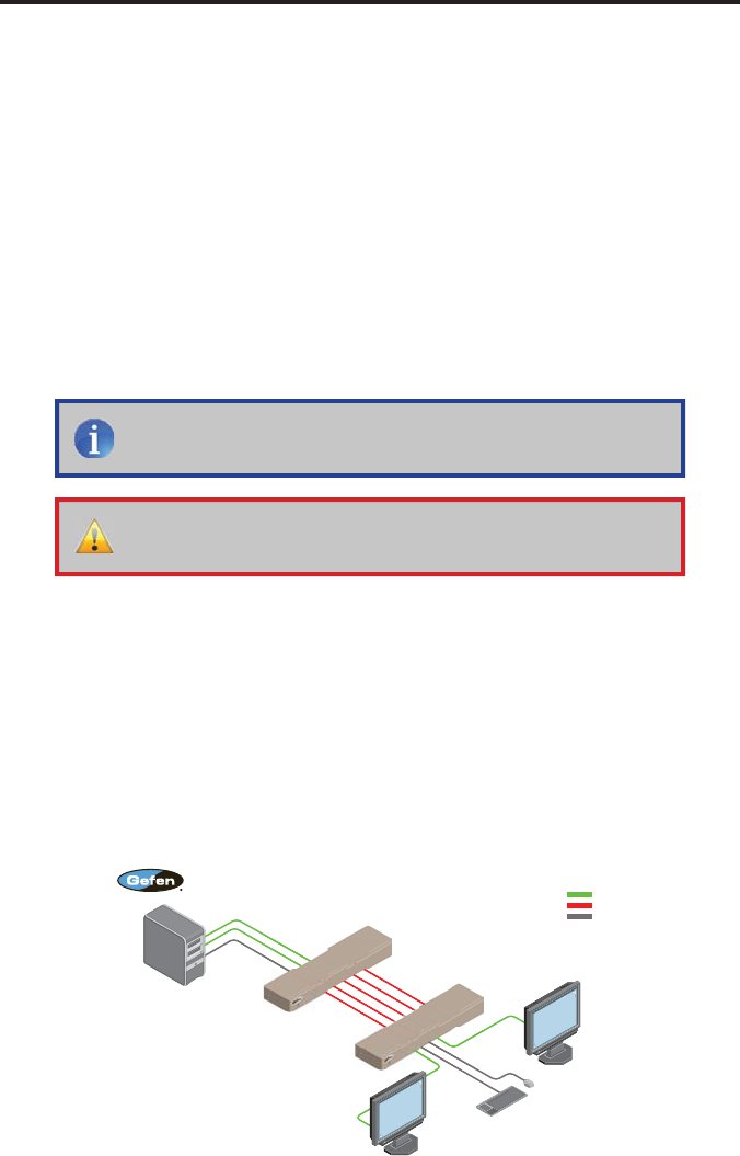
How to Connect the 2x Dual Link DVIKVM Extender Over CAT-6
a
1.
C
onnect the included dual-link DVI cables between the DVI outputs on each
c
omputer and the DVI In
co
nn
ec
t
o
r
s
o
n th
e
2
x D
ua
l Link DVIKVM Ext
e
n
de
r
O
ver
C
AT-
6a
S
ender uni
t
.
2.
C
onnect the included U
S
B cable
f
rom the computer
(
or other U
S
B host
device
)
to the
US
B In port on the
S
ender unit.
3
.
C
onnect
fi
ve
C
AT-
6
a cables between the
S
ender and Receiver units.
Each connector on the
S
ender and Receiver unit is identi
fi
ed as
L
ink
1
.
1
,
L
ink
1
.
2
,
L
ink
2
.
1
,
L
ink 2.2
,
and U
S
B Link
.
When connectin
g
the
C
AT-6
c
ables, make sure that the connectors on the
S
ender unit are connected to
the correspondin
g
connectors on the Receiver unit
(
e.
g
. Link 1.1 --> Link 1.1,
Link 1.2 -> Link 1.2, U
S
B Link --> U
S
B Link, and so on
)
.
4.
C
onnect two dual-link DVI cables
f
rom the Receiver unit to each o
f
the tw
o
dual-link displa
y
s.
5
.
C
onnect up to
f
our U
S
B devices to the
USB Out
ports on the Receiver unit.
t
6
.
C
onnect the included 5V D
C
power supplies to the
S
ender and Receiver
u
nits.
C
onnect the A
C
power cord
f
rom each power suppl
y
to available
e
l
ec
tri
ca
l
ou
tl
e
t
s
.
Wirin
g
Dia
g
ram for the 2x Dual Link DVIKVM Extender Over CAT-6
a
EXT-2DVI-DLKVM-CAT6
Computer
USB Mouse
USB Keyboard
USB CABLE
CAT-6 CABLE
DUAL LINK DVI CABLE
Dual Link DVI Display
2
Dual Link DVI Display
1
Receiver
Sender
NOTE
:
When
fi
eld-terminatin
g
C
AT-6a cables,
f
ollow th
e
TIA
/
EIA-568-B speci
fi
cation outlined on pa
g
e 13.
IMPORTANT
:
When extendin
g
Dual Link resolutions, both
C
AT-6a
c
ables must be exactl
y
the same len
g
th.