4x4 DVI KVM Matrix USER MANUAL www.gefen.
ASKING FOR ASSISTANCE Technical Support: Telephone (818) 772-9100 (800) 545-6900 Fax (818) 772-9120 Technical Support Hours: 8:00 AM to 5:00 PM Monday through Friday PST Write To: Gefen Inc. c/o Customer Service 20600 Nordhoff Street Chatsworth, CA 91311 www.gefen.com gsinfo@gefen.com Notice Gefen Inc. reserves the right to make changes in the hardware, packaging and any accompanying documentation without prior written notice. The 4x4 DVI DL KVM Matrix is a trademark of Gefen Inc. © 2009 Gefen Inc.
TABLE OF CONTENTS 1 Introduction / Operation Notes 2 Features 3 Panel Layout 4 Using the 4x4 DVI DL KVM Matrix 5 RMT16-IR Installation 6 4x4 DVI DL KVM Matrix Configuration 8 RMT-MATRIX-444 Installation 9 RS-232 Interface 10 4x4 DVI Matrix Rack Mount Diagram 11 Specifications 12 Terminology 13 Warranty
INTRODUCTION Thank you for purchasing the 4x4 DVI DL KVM Matrix. Now you can easily switch four cross-platform DVI Dual Link computers to four DVI Dual Link displays. Our 4x4 Dual Link DVI KVM Matrix provides a simple, reliable and highly effective method of creating multiple computer workstations, with each workstation capable of accessing any one of the computers or sources at any time by remote control.
FEATURES Features • Increases your productivity by providing you with access to four computers from four Dual Link workstations • Maintains highest resolution digital video with no loss of quality • Supports either PC or Mac USB keyboards/mice • USB 1.
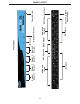
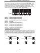
Display 1 Indicator 3 DVI Outputs USB/Audio Outputs IR Extender Eye Port Back Panel Display 4 Indicator CAT-5 Outputs Display 3 Indicator DVI Inputs USB/Audio Inputs Display 2 Indicator IR Sensor Front Panel Connects to 5VDC Power Supply RS232 Controller Port Power Indicator PANEL LAYOUT
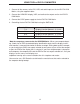
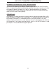
USING THE 4x4 DVI DL KVM MATRIX 1. Connect all the sources to the DVI, USB, and audio inputs on the 4x4 DVI DL KVM Matrix, using the supplied cables. 2. Connect the HDMI/DVI display, USB, and audio to the outputs on the 4x4 DVI DL KVM Matrix. 3. Connect the 5VDC power supply to the 4x4 DVI DL KVM Matrix. 4. Controlling the 4x4 DVI DL KVM Matrix using the RMT16-IR: Pressing Buttons... 1-4 5-8 9-12 13-16 Switches...
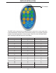
RMT16-IR INSTALLATION LED Indicator The RMT-16-IR remote control will allow the user to select which source each of the 4 connected displays will be viewing. Each of the 4 displays are assigned a group of 4 buttons that correspond to the 4 source inputs. Please use the information below when selecting the desired source for each display.
4X4 DVI DL KVM MATRIX CONFIGURATION The 4x4 DVI DL KVM Matrix has a bank of 8 configuration DIP SWITCHES. These switches are located underneath the unit. Peeling back the black metallic sticker on the bottom of the 4x4 DVI DL KVM Matrix will reveal the Dip Switch bank. These service switches are used for a number of configuration options. By default, all Dip Switches are in the OFF position. Each setting is outlined below.
4X4 DVI DL KVM MATRIX CONFIGURATION AUTOMATIC LINK SELECTION / DUAL LINK ONLY MODE The 4x4 DVI DL Matrix has the ability to run both Single Link and Dual Link DVI sources. There is a feature that will either automatically select the link mode, or lock the unit in Dual Link mode. By default, Dip Switch 3 is in the OFF position (Automatic Link Selection). Turning Dip Switch 3 to the ON position will lock the unit in Dual Link mode and will only allow Dual Link signals to pass properly.
RMT-MATRIX-444 INSTALLATION (OPTIONAL) You can use up to 4 RMT-MATRIX-444 units to extend switching functionality to remote locations. Each unit will allow the user to switch their one display between the 4 inputs on the DVIKVM-444N. Follow these steps for each RMT-MATRIX-444 that will be used in your setup. 1. Connect a CAT5/6 cable between the RMT-MATRIX-444 and one of the CAT5 ports on the rear of the DVIKVM-444N.
RS-232 INTERFACE Binary Table ASCII Corresponding RMT16-IR Button 1 1 2 2 3 3 4 4 5 5 6 6 7 7 8 8 Binary ASCII 0011 0001 0011 0010 0011 0011 0011 0100 0011 0101 0011 0110 0011 0111 0011 1000 9 a b c d e f g Corresponding RMT16-IR Button 9 10 11 12 13 14 15 16 Binary 0011 1001 0110 0001 0110 0010 0110 0011 0110 0100 0110 0101 0110 0110 0110 0111 RS232 Settings Bits per second ....................................................................................................... 19200 Data bits .....
4x4 HDTV MATRIX RACK MOUNT DIAGRAM 10
SPECIFICATIONS Video Amplifier Bandwidth ............................................................................ 165 MHz x 2 Input Video Signal ......................................................................................... 1.2 Volts p-p Input DDC Signal ................................................................................... 5 Volts p-p (TTL) Dual Link Maximum Resolution ....................................................... 3840x2400 @ 60 Hz DVI Connector .......................
TERMINOLOGY DDC Short form for Display Data Channel. It is a VESA standard for communication between a monitor and a video adapter. Using DDC, a monitor can inform the video card about its properties, such as maximum resolution and color depth. The video card can then use this information to ensure that the user is presented with valid options for configuring the display. DDWG Digital Display Working Group DDWG are the creators of the DVI specification. DVI Digital Visual Interface.
WARRANTY Gefen warrants the equipment it manufactures to be free from defects in material and workmanship. If equipment fails because of such defects and Gefen is notified within two (2) years from the date of shipment, Gefen will, at its option, repair or replace the equipment, provided that the equipment has not been subjected to mechanical, electrical, or other abuse or modifications.
*ma-DVIKVM-444DL* Rev A 20600 Nordhoff St., Chatsworth CA 91311 1-800-545-6900 818-772-9100 www.gefen.com Pb fax: 818-772-9120 support@gefen.