
Datasheet


ELECTRICAL RATINGS
SPECIFICATION
DEVICE
TEST CONDITION
FUNCTION
MIN
TYP
MAX
UNIT
Input voltage
18
80
V
Output current
7
A
Input forward current
continuous
HCPL2531
STP, DIR
25
mA
Input forward current
peak
HCPL2531
STP, DIR
50
mA
Input forward voltage
HCPL2531
IF=16mA
STP, DIR
1.45
1.7
V
Input reverse breakdown
voltage
HCPL2531
IR=10uA
STP, DIR
5.0
V
Output current
HCPL2531
STP, DIR
8
mA
Input forward current
continuous
MOCD
EN, RES
60
mA
Input forward current
peak
MOCD
PW=100us,
120pps
EN, RES
1.0
A
Input forward voltage
MOCD
IF=30mA
EN, RES
1.25
1.55
V
Input reverse breakdown
voltage
MOCD
EN, RES
6.0
V
Collector current continuous
MOCD
EN, RES
150
mA
Collector-emitter
breakdown voltage
MOCD
IC=100uA
EN, RES
70
100
V
DC output current
NC7WZ
STPO, FAULT
100
mA
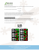
PIN#
FUNCTION
DETAILS
1
GND
Signal Ground
2
STP
The edge of step pulse on this input advances the motor one increment. The size of the
increment is dependent upon the settings of the resolution.
3
DIR
This input is used to change the direction of the motor.
4
+5V
This +5VDC input is used to supply power to the isolated logic inputs.
5
ENABLE
This input is used to enable/disable the output section of the driver. When in a Logic
HIGH state (open), the outputs are enabled.
6
RESET
When LOW, this input will reset the driver (phase outputs will disable).
7
FAULT OUTPUT
This output indicates that a short circuit condition has occurred. This output is active
LOW.
8
FULLSTEP OUTPUT
This output indicates when the driver is positioned at full step. This output can be used
to count the number of full steps the motor has moved, regardless of the number of
microsteps in between.
PIN#
FUNCTION
DETAILS
1
REDUCE CURRENT
Phase Current Reduction Adjustment
2
CURRENT
Phase Current Adjustment
3
GND
Power Ground. The ground, or return, of the power supply is connected here
4
V+
Motor Supply Voltage. +12 to +80VDC
5
~PHB
~PHASE B of the stepping motor
6
PHB
PHASE B of the stepping motor
7
~PHA
~PHASE A of the stepping motor
8
PHA
PHASE A of the stepping motor