
Datasheet


UNDERSTANDING OUTPUTS: FULLSTEP AND FAULT
The two optically isolated and CMOS buffered outputs on the GR214V, FULLSTEP and FAULT, are covered below. Both are
compatible with 5VDC and 3.3VDC logic.
FULLSTEP: The GR214V has an output dedicated to pulsing on every full step location (full current to one winding and zero
current in the other) on the motor, acting somewhat like a tachometer. This means every revolution would be 200 pulses on
the FULLSTEP on a standard 1.8 degree stepper motor.
FAULT: When the GR214V encounters a FAULT state it will put the FAULT pin to a high state. The FAULT conditions that will trip
the drive are:
1.) Cross phasing of the motor windings.
2.) Phase to phase short circuit on the motor connections.
3.) Over current on motor windings.
4.) Reverse polarity on power supply input.
If the GR214V enters a FAULT state you can clear this by cycling the RESET input. This will put the drive back into a normal state,
but if it faults again there may be a problem on the drive or the system.
The FAULT output can be set as a 4800 baud TTL-level UART.
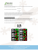
Further FAULT information, including LED blink codes, can be found on Page 13 of this manual.
EXPLANATION OF FEATURES
Sub-Microstepping: At certain microstep resolutions the GR214V will interpolate microsteps between rougher resolution
choices. This means that the motor will move with the smoothness of a higher resolution option but will still have the lower
input frequency requirement of the selected resolution. When operating in 2uStep, 4uStep and 8uStep modes the drive will
interpolate to 16uStep motor smoothness. When operating at 5uStep the GR214V will interpolate to 10uStep smoothness.
Higher levels of interpolation have significantly diminished returns, which is why this affects only lower resolution choices.
Resonance Compensation: Using an entirely new method of motor control allows the GR214V to eliminate nearly all
resonance. The two-tier system the drive uses eliminates resonance at the 1
st
and 2
nd
harmonic and at the midband, increasing
torque and motor stability in unstable step motor regions.
Full Step Morphing: Like all other Geckodrive stepper drives the GR214V has full step morphing. Between 3 – 6 RPS the drive
will morph from microstepping to a true full step output to the motor, increasing high speed motor torque by 40% over a
microstepping only driver. This requires no input from the user and the drive will not need any modifications in the software
controlling it to take advantage of this.
Soft Start: Step motors without a soft start drive operating them can draw significant inrush current. The GR214V ramps up
current to the motor to avoid startup noise and premature tripping of protection circuitry due to sudden current loads.
Spread Spectrum PWM: Most stepper controls have a fixed switching frequency which leads to motor harmonics and large EMI
outputs. With spread spectrum PWM the GR214V switches randomly between switching frequencies at every step, eliminating
harmonic knocking and EMI interference.
Self-Test: A push button is used on the GR214V to allow for quick in-the-field testing of the drive’s core functionality. With a
motor and power supply connected correctly the motor will turn at 1 RPS clockwise and counter-clockwise as long as the
button is held down. This button input will take priority over all other input signals, meaning if STEP and DIRECTION are
connected and the button is held down the GR214V will move in self-test mode.
Protection Circuitry: The GR214V has rugged protection features to prevent damage in the majority of catastrophic events. It is
protected against short-circuit, under-voltage, over-voltage, and over-temperature. The protection circuit will also detect an
open motor phase and an unconnected motor. To clear a FAULT state the RESET input must be cycled to logic ‘0’ for one second
and then returned to a floating or logic ‘1’ state.