
Data Sheet

Thank you for purchasing the G203V drive. The G203V is Geckodrive’s new generation CPLD-based microstep drive. It has short-
circuit protection for the motor outputs, over-voltage and under-voltage protection, over-temperature protection, reversed
power supply polarity protection and will survive accidental motor disconnects while powered-up.
The G203V uses a synchronous PWM design that is absolutely silent when the motor is stopped or turning slowly. It virtually
eliminates stopped-motor heating regardless of power supply voltage. The G203V is a jumper-free drive. There are no internal
user settings at all so there is no need to ever remove the drive cover at all.
The STEP, DIRECTION and DISABLE inputs are optoisolated. All three inputs work with 2.5V, 3.3V or 5V logic drive signals. The
input drive current is now 2.5mA at 2.5V so almost all logic family (74LS, 74HC, etc.) can be used to drive these inputs. The
COMMON return for the signals is controller ground referenced instead of +5VDC. This greatly eases the drive to controller
interface.
There are no unusual STEP to DIRECTION timing restrictions. Stepping occurs on the positive edge of the STEP pulse. The
DIRECTION input must be true 200nS before and after this STEP pulse edge.
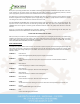
PLEASE READ FIRST BEFORE USING THE G203V
Before you start you must have a 2-phase hybrid PM step motor (ordinary 1.8 or 0.9 degree per step motor), a DC power supply
suitable for the motor and a current set resistor. The motor’s rated phase current must not be more than 7 Amps. The power
supply voltage must be between 15VDC and 80VDC unregulated. The current set resistor may be a 1/4-Watt, 5% part. Finally
have a STEP, DIRECTION and DISABLE (if needed) source available.
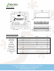
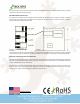
G203V TERMINAL WIRING
The G203V uses a 2-piece modular main connector. The connector is split in two pieces; terminals 1 through 6 (power supply and
motor leads) and terminals 7 through 12 (control interface). Each can be removed separately by pulling the connector body
upwards and off of the mating header pins on the G203V. The connectors must initially be removed to mount the G203V to a
heatsink or chassis.
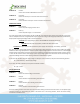
TERMINAL 1 Power Ground
Connect the negative (black) lead of your power supply to this terminal.
TERMINAL 2 Power (+)
Connect the positive (red) lead of your power supply to this terminal. It must be between +18VDC to
+80VDC.
TERMINAL 3 Motor Phase A
Connect one end of your “Phase A” motor winding here.
TERMINAL 4 Motor Phase /A
Connect the other end of your “Phase A” motor winding here.
TERMINAL 5 Motor Phase B
Connect one end of your “Phase B” motor winding here.
TERMINAL 6 Motor Phase /B
Connect the other end of your “Phase B” motor winding here.
TERMINAL 7 Disable
This terminal will force the winding currents to zero when tied to the step and direction controller +5V.
TERMINAL 8 Direction
Connect the DIRECTION signal to this terminal.
TERMINAL 9 Step
Connect the STEP signal to this terminal.