
Operation Manual
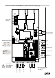


Connexion scheme DC MiniMAX R – 8,2 kOhm resistor logic
D3
PE
L1
L2
L3
U
V
W
11
10
9
8
7
6
5
4
3
2
1
230 400
1 2 3
X4
1 2 3 4 5 6 1 2 3 4
grün
braun
weiß
S02 ZU
S01 Auf
X1
X2
J1
J2
X6
X8
J5
X7
J17
J21
X3
X5
X6
M
J5, J17 and J21
have to be bridged,
if the terminals
X6, X7 and X8
are not in use!
Selection of supply voltage
Bridged =
Automatic run OPEN
Bridged =
Automatic run CLOSE
Supply voltage
230V/50Hz
400V/50Hz
Motor 3 x 230V/50Hz
Motor 3 x 400V/50Hz
OPEN
CLOSE
Limit switch OPEN
Limit switch CLOSE
Optical-electronic
safety edge *
brown
green
white
24V DC 250mA
Safety devices
Impulse input
Pre- limit switch
STOP
OPEN
CLOSE
-
+