
Manual


8
105 Webster St. Hanover Massachusetts 02339 Tel. 781 878 1512 Fax 781 878 6708 www.gearseds.com
Copyright GEARS Educational Systems 2005
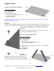
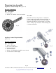
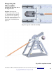
Step Six: Throwing Arm Release Pin
(figure 18)
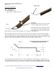
Necessary Components
Qty. Description
1 Hose clamp or zip tie
1 Paper Clip or 4” length of wire rod
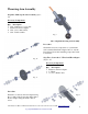
Procedure
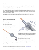
Fashion the paper clip or wire rod into the
release pin shape pictured in figure 20.
Mount the release pin to the throwing arm
by passing the bent wire through the 3/32”
hole in the wood dowel. Secure the release
pin using the hose clamp (pictured in figure 19) or zip ties provided in the kit.
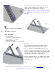
Note: Trebuchet performance and range can be improved by fastening the release pin to the throwing
arm using either duct tape, zip ties or tightly wound elastic bands instead of the hose clamp. Remember
that even a small amount of additional weight at the end of the throwing arm will decrease the net torque
produced by the counterweight and reduce the speed and thus range of the projectile.
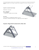
Note: The builder must determine the wood dowel length. There are many ways to optimize the wood
dowel length. Trial and error is one method. A better method is using the GEARS-TrebStar™ simulator
to make and test iterative designs in an effort to optimize both the dowel length and the projectile length.
Fig.18
Fig.19
Drawing showing the approximate bend
configuration of the release pin.
Release Pin
Fig.20