
Manual


7
105 Webster St. Hanover Massachusetts 02339 Tel. 781 878 1512 Fax 781 878 6708 www.gearseds.com
Copyright GEARS Educational Systems 2005
Procedure
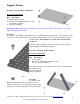
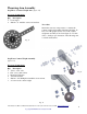
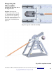
Obtain the necessary components to construct the counter weight assembly illustrated in figure 15.
Connect the fishplate to the steel counter weight using the #10-24 x ½”screw, washers and nut as shown
in the illustrations (Top and left).
Attach the fishplate and counter weight assembly to the end of the counter weight arm by passing the 1-
1/2” axle through the arm members and fishplate. Capture the fishplate inboard between the two 7-hole
angles. The fishplate should hang in between the 7-hole angles in such a way as to swing freely through
270 degrees of revolution or more.
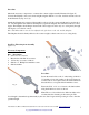
Note: Add #10 washers as needed to adjust for side play between the axle and the fishplate.
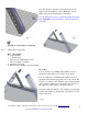
The fishplate should be firmly affixed to the counter weight so that it cannot move or swing freely.
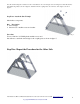
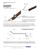
Step Five: Throwing Arm Assembly
(figure 16)
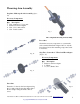
Necessary Components
Qty. Description
1 5/16 x 18” wood dowel.
1 Mast holder with #10-24 set screws
2 1/8”hex key set screws ¼-20x ¼”
2 #10-24 x ½” Phillip head machine screws
2 #10 flat washers
Procedure
Secure the mast holder to the 3” wheel using 2 #10-24 x
½” machine screws and washers as shown in figures 16-
17. Hex nuts are not required since the shaft retainer has
threaded holes to accept the #10-24 machine screws.
Fasten the 5/16” x 18” wood dowel to the shaft retainer
using the #10-24 set screws as shown.
Note: The wood dowel has holes drilled at either end to
accommodate the fastening of the release pin. The
dowel length is determined experimentally by the user. Start longer and keep testing in order to find the
optimum length.
Fi
g
. 16
Fi
g
. 17