
Manual


6
105 Webster St. Hanover Massachusetts 02339 Tel. 781 878 1512 Fax 781 878 6708 www.gearseds.com
Copyright GEARS Educational Systems 2005
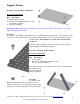
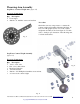
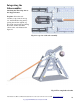
Throwing Arm Assembly
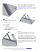
Step Three: Counter Weight Arm (figure 12)
Necessary Components
Qty. Description
2 7 hole angles.
2 #10-24 x ¾” machine screws and washers
Procedure
Obtain the necessary components to construct the
counter weight arm assembly illustrated in figure 12.
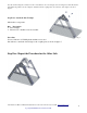
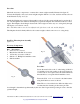
Note: An orthographic (front) view of the counter
weight arm assembly is shown in figure 13. Use this
view to obtain proper orientation of the throwing arm,
3” wheel and fasteners.
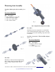
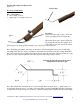
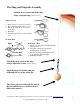
Step Four: Counter Weight Assembly
(figure 14)
Necessary Components
Qty. Description
1 3/16” x 1-1/2” axle.
2 3/16” (bore) shaft collars
1 180 degree fish plate
4 3/16” flat washers
1 #10-24 x 1/2” Phillip head machine screw and nut
1 9.8 ounce steel counter weight
Fi
g
. 14
Fi
g
. 15
Fi
g
. 13